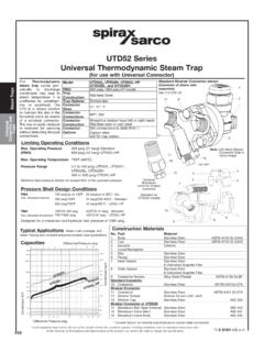
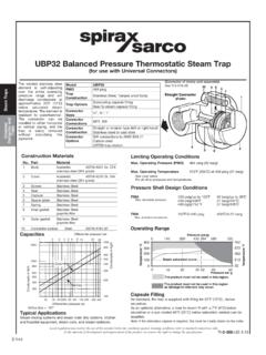
Transcription of TD32F FLANGED THERMODYNAMIC STEAM TRAPS
1 IM-P068-26 ST Issue 41TD32 FFlanged THERMODYNAMIC STEAM TrapsInstallation and Maintenance InstructionsIM-P068-26ST Issue 40683150/4 IFq 2 PFq 2 QFs RFg SFy TFw UF 2 Printed in the UK Copyright 2003IM-P068-26 ST Issue 42IF2q 2 2 Safe operation of this unit can only be guaranteed if it is properly installed,commissioned and maintained by a qualified person (see Section 11 of the attachedSupplementary Safety Information) in compliance with the operating instructions. Generalinstallation and safety instructions for pipeline and plant construction, as well as theproper use of tools and safety equipment must also be complied whether closing isolating valves will put any other part of the system orpersonnel at risk. Dangers might include; isolation of vents and protective devices oralarms.
2 Ensure isolation valves are turned off in a gradual way to avoid system attempting any maintenance consider what is or may have been in the that any pressure is isolated and safely vented to atmospheric pressure beforeattempting to maintain the product, this is easily achieved by fitting Spirax Sarcodepressurisation valves type DV (see separate literature for details). Do not assumethat the system is depressurised even when a pressure gauge indicates time for temperature to normalise after isolation to avoid the danger of burns andconsider whether protective clothing (including safety glasses) is product is recyclable. No ecological hazard is anticipated with the disposal of thisproduct providing due care is ST Issue 43PF2q 2 2 General descriptionThe TD32F is a maintainable medium pressure FLANGED THERMODYNAMIC STEAM trap which hasan integral strainer screen fitted to protect the internals from TD32 FLC is designed specifically for low load applications such as STEAM mains TD32FA and TD32 FALC are fitted with an anti-air-binding disc to ensure prompt removal ofair on extrasInsulating cover (for the DN15 and 20 only): To prevent the trap being unduly influencedby excessive heat loss such as when subjected to low outside temperatures, wind, rain.
3 The insulating cover, if required, must be specified at the time of order product fully complies with the requirements of the European Pressure EquipmentDirective 97 / 23 / products are available with certification to EN 10204 Note: All certification / inspectionrequirements must be stated at the time of order : For additional information see the Technical Information Sheet and pipe connectionsDN15, 15LC, 20, 20LC, 25 and 25 LCFlanged ANSI B Class 150 and 300, DIN 2501 PN40 and JIS / KS 10, 16 and 1 TD32 FFig. 2 The TD32 FLC and TD32 FALC versionsare identified by the groove in the capFig. 3 The TD32FA and TD32 FALC have an anti-air-binding discIM-P068-26 ST Issue Limiting conditions (ISO 6552)Body design conditionsPN40 PMA - Maximum allowable pressure40 bar g(580 psi g)TMA - Maximum allowable temperature400 C(752 F)PMO - Maximum operating pressure32 bar g(464 psi g)TMO - Maximum operating temperatureTD32F and TD32 FLC400 C(752 F)TD32FA and TD32 FALC255 C(491 F)Minimum operating pressure for satisfactory bar g ( psi g)PMOB - Maximum operating backpressure is 80% of the upstream pressureDesigned for a maximum cold hydraulic test pressure of:60 bar g(870 psi g) Operating rangeThe product must not be used in this region.
4 *PMO Maximum operating pressure for saturated STEAM service is 32 bar g (464 psi g).PMOB Maximum operating backpressure is 80% of the upstream :Minimum operating pressure for satisfactory operation is bar g ( psi g).A- BTD32F and TD32 FLCC- BTD32FA and TD32 FALC Pressure bar gTemperature CSteamsaturationcurveACBIM-P068-26 ST Issue 45 Note: Before actioning any installation observe the 'Safety information' in Section to the Installation and Maintenance Instructions, name-plate and Technical InformationSheet, check that the product is suitable for the intended materials, pressure and temperature and their maximum values. If the maximumoperating limit of the product is lower than that of the system in which it is being fitted,ensure that a safety device is included in the system to prevent the correct installation situation and the direction of fluid protective covers from all trap should preferably be installed in the horizontal plane, with a small drop legpreceding it.
5 Suitable isolation valves must be installed to allow for safe maintenance andtrap replacement. Consideration should be given to a suitable method for testing the correctoperation of the trap. This may be a sight glass or a Spiratec system. Sight glasses must bepositioned a minimum of 1 m (3 ft) downstream of any blast-action TRAPS . Where the trapdischarges into a closed return system, a non-return valve should be fitted downstream toprevent return flow. Remove all packaging and protective covers and ensure all connectionports are clear from open isolation valves slowly until normal operating conditions are achieved - this willavoid system shocks. Check for leaks and correct operation. Always ensure the correcttools, safety procedures and protective equipment are used at all : If the trap is to discharge to atmosphere ensure it is to a safe place, the discharging fluidmay be at a temperature of 100 C (212 F).
6 QF2s After installation or maintenance ensure that the system is fully functional. Carry out tests onany alarms or protective SF2y The THERMODYNAMIC STEAM trap will discharge condensate with a blast type action at a fewdegrees below STEAM saturation temperature, due care must be given to the site ofthe ST Issue 46 Table 1 Recommended tightening torquesorItem PartN m(lbf ft)mmDN15LC36 A / F135 - 150(100 - 110)2 CapDN1536 A / F180 - 200(132 - 147)DN2041 A / F180 - 200(132 - 147)DN2555 A / F250 - 275(184 - 202)5 Strainer cap32 A / FM28170 - 190(125 - 140)TF2w Note: Before actioning any maintenance programme observethe 'Safety information' in Section General informationBefore undertaking any maintenance on the trap it must be isolated from both the supply line andreturn line and any pressure allowed to safely normalise to atmosphere.
7 The trap should then beallowed to cool. When reassembling, ensure that all joint faces are How to service-Remove insulating cover (7) , if fitted, and unscrew the cap (2) using a suitable spanner or not use stillsons or a wrench of similar type which may cause distortion of the the seating faces on the body are only slightly worn, they can be refaced by lapping on a flatsurface, such as a surface plate. A figure-of-eight motion and a little grinding compound, suchas 'Carborundum Co's Compound ' gives the best results. If the wear is too great to berectified by simple lapping, the seating faces on the body must be ground flat and then : the disc (3) should always be replaced with a new one. The total amount of metalremoved in this way should not exceed mm ( ").-When reassembling, the disc (3) is normally placed in position with the grooved side in contactwith the body seating on the cap (2) to the recommended tightening torque (see Table 1); no gasket isrequired but a suitable high temperature anti-seize grease should be applied to the How to clean or replace the strainer:-Unscrew the strainer cap (5) using a suitable the screen (4) and clean or, if damaged, replace with a new reassemble, insert the screen (4) into the strainer cap (5), then screw the strainer cap into fine smear of 'Molybdenum Disulphide' grease should be applied to the first few should be taken to ensure that the gasket and gasket faces are to the recommended torque (see Table 1).
8 -When maintenance is complete open isolation valves slowly and check for ST Issue 47UF2 2 The spare parts available are shown in heavy outline. Parts drawn in broken line are notsupplied as sparesDisc for TD32F or TD32 FLC (packet of 3)3 Disc, strainer screen and gasket for TD32FA or TD32 FALC3, 4, 6 Strainer screen and gasket4, 6 Strainer cap gasket (packet of 3)6 Insulating cover (for the DN15 and 20 only)7 How to order sparesAlways order spares by using the description given in the column headed 'Available spares'and state the size and type of : 1 - Strainer screen for a DN15 Spirax Sarco TD32F THERMODYNAMIC STEAM 4734*26*5* Note: Items 2 and 5 arenot available as ST Issue 48