Transcription of SIDE CHANNEL BLOWERS - Seko
1 side CHANNEL BLOWERS innovation > technology > futureSide CHANNEL BLOWERS2water and industry > side CHANNEL blowersOperating principleThe side CHANNEL blower or exhauster increases the pressure of the aspirated gas by the creation, in the peripheral toroidal CHANNEL , of a series of vortex caused by the centrifugal thrust of the the impeller is rotating, the vanes force the gas forward and, because of the centrifugal thrust, outwards, producing a helical motion. During this motion, the gas is recompressed repeatedly with a conseguent linear pressure increase along the length of the and advantagesThe side CHANNEL blower are suitable for all those applications requiring considerably higher pressuers than that which can be achieved using centrifugal fans. side CHANNEL exhausters are used in all those applications requiring an operating vacuum higher than the achievable by a fan, but not as high as to require the use of a vacuum rotating parts are not in contact with the casing.
2 There is thereforeno friction during operation and thus no internal lubrification is necessary. The gas moving through the machine therefore remains uncontaminated and completely oil-free. The other main advantages of using side CHANNEL machines are: easy installation low noise level non vibration and therefore complete dynamic stability pulsation free discharge minimal maintenanceAccessoriesA complete range of accessories is available for all machines:cartridge type filters for BLOWERS / in-line filters for exhausters / flexible hoses / non return valves / pressure relief valves for BLOWERS / vacuum relief valve s for exhausters / pressure and vacuum gauges / acoustic principle Casing and impellers are made of aluminium alloy. The standard machines for air are manufacturated in the so-called CLOSE COUPLED versione; a flange mounted electric motor is bolted to the machine casing. The impeller, which is dynamically balanced, is fitted directly onto the motor shaft extension.
3 The two-pole electric motors, designed for continuous operation, are available in three phase for allthe powers shownin the catalogue and in single phase up to 2,2 kW. They are manufactured according to IEC Specifications with the following standard features: - for machines with BLxxx010/020 suffix degree of protection: - IP55 insulation class: - F for powers up to 3 kW - H for powers 4 kW and above line voltage:- three phase motors, at 50 Hz 230 V / 400 V for powers up to 3 kW 400 V / 690 V for powers 4 kW- three phase motors, at 60 Hz 265 V / 460 V for powers up to 3,6 kW 460 V / 795 V for powers 4,8 kW- single phase motors, at 50 Hz 230 VFor 50 Hz supply, the allowed voltage variation is 10% according to IEC 38 60 Hz supply, as well as for motors specifically requested, for any other voltage at 50 Hz or at 60 Hz, a 5% tolerance on supply voltage is allowed, in accordance with IEC 34 Specification.
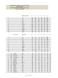
4 - for machines with BLxxx001/002 suffix degree of protection: - IP54 insulation class: - F line voltage:- three phase motors, at 50 Hz 200 V / 345~416 V for powers up to 4 kW 345~415 V / 600~720 V for powers > 4 kW- three phase motors, at 60 Hz 208 V / 380~480 V for powers up to 4,6 kW 380~480 V / 660~720 V for powers > 4,6 kW- single phase motors, at 50 Hz and 60 Hz 104~127 V / 208~254 V The machines meet the requirements of the European Directives 2006/42 (Machines), 2006/95 (Low Voltage), 2004/108 (Electro-magnetic Compatibility) and the applicable harmonised Standards. For the handling of gases other than air, steam, indistrial gases and mixture of explosive gases, special gas tight units can be manufactured. In case of corrosive gases, all the internal parts can be treated or lined with protecting coatings.~240~275 side CHANNEL BLOWERS3innovation > technology > futureBLOWERS ingle StageSingle ChannelSingle ImpellerBLOWERD ouble StageDouble ChannelDouble ImpellerBLOWERD ouble StageDouble ChannelSingle ImpellerFlow rates refer to air at the suction conditions of 20 C and 1013 mbar available upon requestTOLERANCE ON FLOW RATE VALUES: 10%[ ] BL040 THREE PHASES MOTOR: 0,9 KW - SINGLE PHASE MOTOR: 0,8 KW[ ] BL420 THREE PHASES MOTOR: 1,6 KW - SINGLE PHASE MOTOR.
5 1,5 KW05010015020025030035040045050055060065 0 Outlet pressure hPa= mbarFlow rateMotor power3m/h3m/hkW3m/hkW3m/hkW3m/hkW3m/hkW3 m/hkW3m/hkW3m/hkW3m/hkW3m/hkW3m/hkW3m/hk W3m/hkWBL020BL030BL040BL050BL060BL080BL2 20BL420BL820BL012BL014BL017BL020BL023BL0 30BL036BL042BL04954841502123005188615454 8130160205235280350410525600225411818226 8472721385201141421892162543283874965600 ,220,40,9 [ ]1,52,240,81,6 [ ]7,51,11,12,22,23345,55,53[ 0 m/h at 70 mbar ]248915123042658122499100127173200233306 3634705300,40,9 [ ]1,52,240,80,6 [ ]7,51,11,12,22,23345,55,5591161923804410 6474871141581862152853404455040,9 [ ]1,52,240,80,6 [ ]7,51,11,12,22,23345,55,53[ 6 m/h at 130 mbar ]308215533431904517510214317420026831742 04781,11,5340,80,6 [ ]7,51,51,52,22,23345,55,5501172881674428 65911271621862522943954542,235,50,81,6 [ ]7,51,51,533345,57,57,582242584035781112 15017423627337043045,52,27,51,52,233445, 57,57,5196423784972100138162220255346408 7,52,27,52,22,23345,57,57,57,51502635442 63891251502042383223887,52,2112,22,2345, 55,57,57,59,2330355480113138188222298370 112,23445,57,57,59,29,230628477310112617 2206274352113345,55,57,57,59,21127821416 789114157190250334113345,55,57,59,211112 5077102142174225317115,57,57,59,21115300 15BL72032430632883270325232344,32164,319 84,31805,51625,51445,51267,5BL5202362203 2033185316731493131311339537743[ 65 m/h at 480 mbar ]Performance table50 Hz 2900 rpmFlow rate-Pressure diagramBL023BL049BL020BL030BL036BL042BL8 20BL060BL012BL014BL017BL420BL080BL220BL0 60BL050BL040BL030BL020020406080100150200 2503003504004505006007008009001000110012 0013005010015020025030035040045050055060 0650 Outlet pressure [hpa = mnar]KeyBlower typeMotor power [kW]
6 7,57,55,59,21111153345,5117,59,22,249,25 ,52,22,237,57,5347,57,51,5445,55,50,82,2 1,61,5335,55,51,12,21,52,23441,11,52,20, 91,10,40,224BL7207,55,54,33BL52043 DimensionsC 2 QNAGGHMB 1PR FDILOEfig. 3 Double STAGE - Double CHANNEL - Double IMPELLERBL220BL420BL520BL820 ( kW)Double STAGE - Double CHANNEL - Double IMPELLERBL720BL820 (11 kW)fig. 2fig. 1 Single STAGE - Single CHANNEL - Single IMPELLERBL020 BL030BL040 BL050BL060 BL080fig. 4AC 2 QNGGHMB 1 PRDILOE FB 2 1 ECDILPO FGGHMANA*R*Q*B 2 1 PECDILO FANHGGMD ouble STAGE - Double CHANNEL - Single IMPELLERBL012 BL014BL017 BL020BL023 BL030BL036 BL042BL049235228903510127619021045401"10 ,724724690391013832052195411,72502102633 10204water and industry > side CHANNEL blowersBL020BL030BL040BL050BL060BL080BL2 20BL420BL820 (7,5 KW)BL820 (11 KW)BL012BL014BL017BL020BL023BL030BL036BL 042BL049 blower TypeReference figureABCDEF GHILMNOPQRSC onnection ("Gas)outlet 2inlet 1 Weight(kg)2,52,51" 1"1" 1"1" Fig.
7 1 Fig. 1305286115451217,59522525548301833533312 04814201152602951252627024031534530341" 2"1" 2"Fig. 1 Fig. 1385382125481520140290325110302"41,55094 51152651523,5170356394114683953804774623 54,562" 2" Fig. 1 Fig. 127031590391012,58320523063301" 14315355116461216,5952252565127320289400 314302,531" 1" 1" Fig. 2 Fig. 2424435126501420140290325864589424435154 941420140290325225107532451590595454,54, 5 Fig. 2 Fig. 3440370130799100160288328-351" 42440370130799100160288328-4244519445193 5552"1" 2"Fig. 4 Fig. 447040016090910016034738770352" 5449041616090910016034738770560225502235 552" Fig. 4 Fig. 4515440160909100160347387703552044018097 116033040045012088590227002245553"3"Fig. 4 Fig. 455046618097116033040045012067522455 Fig. 4615505180107116033042047018545640532180 107116033042047018576517750174555 Fig. 4 Fig. 4106534515454016476761646854066402"57068 52" 662" 2" 822" 903"3"1063"3"4"4"112 Dimension [mm]Weights shown are for the machines fitted with the largest motor powerBL520371410120481420115260295972750 04043042"2"Fig.
8 256144645BL72042443515494142014029032522 577590595454,52"2"Fig. 3761646852" 2" 2" 2" AccessoriesMembrane diffuserPropertyUnitValueDisc Classinch9/12 Air Flow3m/h2-8/2-10 Maximum Air FlowN3m/h12/15 Total Diametermm270/340 Perforated Diametermm230/312 Perforated (DIN 53479)3 Strength (DIN 53504) at Break (DIN 53504)%>500 Tear Strength (DIN 53507)N/mm>7 Hardness (DIN 53505)Shore A50 5 Operating Temperature C-30/+130 Tensile Value (at 100% extension after 24 h)<%5 Membrane Thicknessmm2 SpecificationEPDM (DuPont)Support Plate MaterialPP GFR30 (Basell)ADD 230/ADD 300 Disc Diffuser Technical DataActivated sludge process is the main stage of modern wastewater treatment technology. Aeration systems which are key component of the activated sludge process serve two purposes; satisfy oxygen demand and provide sufficient mixing turbulence to keep solids in must be provided in biological activated sludge wastewater treatment systems to satisfy several types of demands: Organic oxygen demand that can be further divided into oxygen required for cell synthesis and oxygen required for endogenous respiration.
9 Biological oxidation of ammonia nitrogen Oxidation of certain inorganic materials that may be present in the " Weight0,8BL0401" 1,3BL0502"2,0BL060BL4201" 2,0BL0802" 3,5BL0142,2BL017BL020BL023BL0302,4BL036B L042BL049 ModelSF5 NGSF6 NGSF7 NGSF7 NGRSF10 NGRSF8/1 GSF10/1 GSF14G7,5 CartridgeC6C6C8C8C10C8C10C14 Filters1" Weight0,851"1,02"1,71" 1,153,5 ModelSVR5 SVR6 SVR7 SVR6 SVR10 Non ReturnValvesModel2"2,0SF7 NGC82"1,7 SVR72,0SF8/1 GSVR72,2SF8/1GC82,2SF8/1GC82,4SF10/1GC10 SF14G7,5C142"1,72" 2,5 SVR82" 2,5 SVR82" 2,5 SVR82" 2,5 SVR83"3,5 SVR103"3,5 SVR103"6,0 SVR154"1" Weight1,61" 1,22" " 1,5 ModelSVS5/6 TSVS6 TSVS7 TSVS6 TSVS10 Pressure ReliefValves2" WeightModelSVS6 TSVS7 TSVS6 TSVS10 Pressure ReliefValvesSVS7 TSVS8 SVS8 TSVS8 SVS10 SVS10 SVS15 WeightModelPressure ReliefValves1" Weight1"2"1" ModelSM5SM6SM7SM6SM10 Flexible hoses2"SM7SM82"SM72" SM82" SM82" SM82" 3"SM103"SM103"SM154"FiltersBL0401" 1,3SF6 NGC61"1,0 SVR61" 1,2 SVS6 TSVS6T1"SM6BL0401" 1,3SF6 NGC61" 1,15 SVR61" 1,5 SVS6 TSVS6T1" SM6BL020BL030SF5 NGSF4 NGSM5SM4 SVS5/6 TunavailableSVR5 SVR4 SVS6 TBL820SF10NG2" " SM8BL0122,0SF8/1 GSVR61" 1,15 SVS61" SM62" " 0,81" 0,851" 1,61" Single StageSingle ChannelSingle ImpellerDouble StageDouble ChannelDouble ImpellerDouble StageDouble ChannelSingle Impeller5innovation > technology > futureBL520BL720SF8 NGRSVR7 SVR7 SVS7 TSVS7 TSM7SM7SF10 NGR2"1,72"1,72"2"2" " "3,12"3,9C8C8C101"0,61" " " " " " " " " "Membrane DiffuserFine pore diffusion is a subsurface form of aeration in which air is introduced in the form of very small bubbles.
10 There has been increased interest in fine pore diffusion of air as a competitive system due to its high Oxygen Transfer Efficiency (OTE). Smaller bubbles result in more bubble surface area per unit volume and greater aeration systems can be classified into three categories:- Porous (Fine Bubble) Diffusers: Concept of the fine bubble corresponds to the size of 1- 3 mm. These diffusers come in various shapes and sizes, such as discs, tubes, domes, and Nonporous (Coarse Bubble) Diffusers: These are in the form of perforated piping, spargers etc. The bubble size of these diffusers is larger than the porous diffusers (larger than 10 mm), thus lowering the Other Diffusion Devices: Jet aerators, aspirators, and U of the Diffused Aeration SytemThe performance of diffused aeration systems under normal operating conditions is directly related to the following parameters:- Wastewater characteristics,- Process type and flow regime,- Loading conditions,- Basin geometry,- Diffuser type, size, shape, density, and airflow rate,- Mixed liquor dissolved oxygen control and air supply flexibility,- Mechanical integrity of the system,- Operator expertise,- Fouling,- The quality of the preventive operation and maintenance per diffuser [Nm /h]45670 Oxygen Transfer Efficiency [%]102030406 diffusers/m 1 diffuser/m 505 m4 m3 m6 mSeko sends the equipments which are bought by you and thus usage period of the products will be started.