Transcription of SD-23-7541 Bendix ADB 22X , ADB 225 , SN6 , SN7 , …
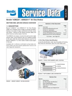
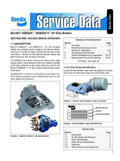
1 1 Bendix ADB 22X , ADB 225 , SN6 , SN7 , SK7 Air disc Brakes SD-23-7541 DESCRIPTIONB endix Air disc Brakes use a floating caliper design to provide foundation braking on all axles of heavy commercial vehicles, buses and trailers. Bendix Air disc Brakes provide safety and performance, as well as ease of service. Available in models with or without a combination spring brake unit, these brakes may also include optional wear sensors and/or wear diagnostic Air disc Brakes convert air pressure into braking force. (See Figure 2.) When the vehicle brakes are applied, air enters the service brake chamber through the supply port, applying pressure within the diaphragm. The pressure expands the diaphragm, applying force to, and moving the pressure plate and pushrod forward.
2 The pushrod acts against a cup in the internal lever which pivots on an eccentric bearing moving the bridge. Moving against a return spring, the bridge transfers the motion to two threaded tubes and tappets, which move the inner brake pad. The inner brake pad (from its normal position of having a running clearance between it and the rotor) moves into contact with the brake rotor. Further movement of the bridge forces the caliper, sliding on two stationary guide pins, away from the rotor, which pulls the outer brake pad into the rotor. The clamping action of the brake pads on the rotor applies braking force to the Release and AdjustmentWhen the vehicle brakes are released, the air pressure in the service brake chamber is exhausted and the return springs in the chamber and the bridge return the air disc brake to a neutral, non-braked position.
3 To maintain the running clearance gap between the rotor and the brake pads over time, the non-braked position is mechanically adjusted by a mechanism in the caliper. The adjustment mechanism operates automatically whenever the brakes are activated, to compensate for rotor and brake pad wear and to keep the running clearance constant. During pad or rotor maintenance, the technician manually sets the system s initial non-braked position. The total running clearance (sum of clearances on both sides of the rotor) should be between to in. ( and mm).FIGURE 1 - Bendix ADB 22X AIR disc BRAKEFIGURE 2 - CROSS-SECTION VIEW SHOWING brake OPERATIONS upply Port Return Spring PushrodLeverOuter brake PadInner brake PadRotor Eccentric Bearing Service brake ChamberBridgePressure PlateDiaphragm2 SAFE MAINTENANCE PRACTICESWARNING!
4 PLEASE READ AND FOLLOW THESE INSTRUCTIONS TO AVOID PERSONAL INJURY OR DEATH:When working on or around a vehicle, the following general precautions should be observed at all times:1. Park the vehicle on a level surface, apply the parking brakes, and always block the wheels. Always wear safety glasses. Where specifically directed, the parking brakes may have to be released, and/or spring brakes caged, and this will require that the vehicle be prevented from moving by other means for the duration of these Stop the engine and remove ignition key when working under or around the vehicle. When working in the engine compartment, the engine should be shut off and the ignition key should be removed. Where circumstances require that the engine be in operation, EXTREME CAUTION should be used to prevent personal injury resulting from contact with moving, rotating, leaking, heated or electrically charged Do not attempt to install, remove, disassemble or assemble a component until you have read and thoroughly understand the recommended procedures.
5 Use only the proper tools and observe all precautions pertaining to use of those If the work is being performed on the vehicle s air brake system, or any auxiliary pressurized air systems, make certain to drain the air pressure from all reservoirs before beginning ANY work on the vehicle. If the vehicle is equipped with an AD-IS air dryer system or a dryer reservoir module, be sure to drain the purge Following the vehicle manufacturer s recommended procedures, deactivate the electrical system in a manner that safely removes all electrical power from the Never exceed manufacturer s recommended pressures. 7. Never connect or disconnect a hose or line containing pressure; it may whip. Never remove a component or plug unless you are certain all system pressure has been Use only genuine Bendix replacement parts, components and kits.
6 Replacement hardware, tubing, hose, fittings, etc. must be of equivalent size, type and strength as original equipment and be designed specifically for such applications and Components with stripped threads or damaged parts should be replaced rather than repaired. Do not attempt repairs requiring machining or welding unless specifically stated and approved by the vehicle and component Prior to returning the vehicle to service, make certain all components and systems are restored to their proper operating For vehicles with Antilock Traction Control (ATC), the ATC function must be disabled (ATC indicator lamp should be ON) prior to performing any vehicle maintenance where one or more wheels on a drive axle are lifted off the ground and : Not all wheels and valve stems are compatible with Bendix Air disc Brakes.
7 Use only wheels and valve stems approved by the vehicle manufacturer to avoid the risk of valve stem shear and other compatibility DUST WARNING: AVOID CREATING DUST WHEN WORKING WITH brake PADS DUE TO POSSIBLE CANCER AND LUNG DISEASE Bendix Spicer Foundation brake LLC does not offer asbestos-containing brake linings or disc pads, the long-term effects of certain non-asbestos fibers have not been determined. Current OSHA Regulations cover exposure levels to some, but not all, components of non-asbestos linings and pads. The following precautions should be used when handling these materials: Avoid creating dust. Compressed air or dry brushing must never be used to clean brake assemblies or the work area. brake workers must take steps to minimize their exposure to airborne brake lining particles.
8 Procedures to reduce exposure include: working in a well-ventilated area, segregating areas where brake work is performed, using local filtered ventilation systems or enclosed cells with filtered vacuums for all brake work. Respirators approved by the Mine Safety and Health Administration (MSHA) or National Institute for Occupational Safety and Health (NIOSH) should be worn at all times during brake servicing. Workers must wash before eating or drinking, should not use tobacco products in any form, shower after working, and not wear work clothes home. Work clothes should be vacuumed using a high efficiency particulate filter (HEPA) vacuum and laundered separately without shaking. OSHA Regulations regarding testing, disposal of waste and methods of reducing exposure for asbestos are set forth in 29 Code of Federal Regulations These Regulations provide valuable information which can be utilized to reduce exposure to airborne particles.
9 Material Safety Data Sheets on Bendix air disc brake pads, as required by OSHA, are available from Bendix Spicer Foundation brake .. 1 Safe Maintenance Practices.. 2 Air disc brake Sectional and Exploded Views..4-5 Air disc brake Identification.. 6 Rotor Identification.. 6 Electronic Wear Indicator Exploded Views.. 6 Preventive MaintenancePreventive Maintenance Schedule.. 7 Running Clearance Inspection.. 7 Mechanical Wear Indicators..8-9 Electronic Wear Indicators, including Hand Held Diagnostic Equipment .. 10 TroubleshootingTroubleshooting Flowchart.. 11 InspectionsBrake Pads.. 12 Rotors.. 13 Caliper Running Clearance .. 14 Adjuster Mechanism.. 15 Guide Pins ..16-17 Maintenance ProceduresPad Replacement..18-19 Electronic Wear Indicator Replacement.
10 20-21 Tappet and Boot Assemblies Replacement ..22-24 Carrier/Caliper Assembly Replacement.. 25 brake Actuator and Spring brake Replacement ..26-27 SERVICE DATA INDEX4 FIGURE 4 - SECTIONAL VIEW1 Caliper2 Carrier5 Guide Pin13 Tappet and Boot Assembly17 Bridge23 Adjuster Unit24 Turning26 Spring Clip27 Spring7 Brass Bushing9 Inner Boot10 Cover11 Pad Retainer12 PadAssembly16 Threaded Tube22 Inner Seal30 Chain 32 Chain Wheel161 Tappet Bushing61 Shear Adapter68a Cap 58 Ring45 Washer 44 Pad Retainer Pin40 Caliper Bolt 37 Adjuster Cap33 Wear Sensor 22 Inner16 Threaded Tube161 Tappet13 Tappet and Boot Assembly4aGuide Pin18/1 Spring brake or18/2 brake Chamber19 Lever20 Eccentric Bearing 46 Rotor43 BoltPad Assembly 1217 Bridge 12 Pad Assembly27 Spring6c Guide Sleeve 2 Carrier4cGuide Pin9 Inner Boot58 Ring39cCaliper Bolt68cCover39aCaliper Bolt6aRubber Bushing4bGuide Pin6bRubber