Transcription of Cooling incubator with controlled humidity …
1 CLIMACELL 111, 222, 404, 707 Instructions for useCooling incubatorwith controlled on obtaining the new Cooling incubator with controlled humidity . It is intended for applications where change of sample temperature and relative humidity in various time modes is temperature run is controlled by a modern microprocessor (Fuzzy-Logic) with a digital display and a PT 100 thermostat sensor. This system ensures high accuracy of temperature regulation and reliability of the tempering units comply with the technical and legislative requirements and have been designed in accordance with the respective EN standards. The units are made of high quality materials using the latest technology. Each unit undergoes a careful output you follow the instructions mentioned here, the unit will become your reliable and powerful these advantages will be available just for you. This unit will help you to solve your everyday problems and will certainly become a powerful assistant for you.
2 This unit is very easy to use; nevertheless, we recommend you to read the Instructions for use carefully to be able to use all the advantages of this unit and had complete knowledge for its optimal :12. 4. 20111 GENERAL AND PUTTING INTO AND OTHER OF THE Cooling incubator with controlled CONNECTOR RS-232C FOR PROTOKOL AND CONNECTING TO THE WATER SOURCE AND TO THE ELECTRIC THE UNIT GENERAL SETUP OF ACTIVATING THE SERVICE SERVICE01 STORING P1 P6 .. SERVICE02 RESTORE/UPLOAD THE PROGRAMS FROM THE CHIP CARD TO THE SERVICE03 SET THE REAL TIME AND SERVICE04 SET INTERVAL ON SERVICE05 SELECT SERVICE06 SETTING OF THE INNER SOCKET (OPTIONAL)AND FAN SERVICE 07 SETTING THE SAFETY SERVICE41 SETTING THE TEMPERATURE SERVICE56 ADJUSTABLE MONITORED DEVIATION OF THE RH VALUE FROM THE SERVICE58 DOOR SERVICE62 ALARM SETTING.
3 SERVICE64 P6 PROGRAMME SERVICE09 CANCELING THE SERVICE SETTING THE SERVICE60 RACKS with EXPOSURE LIGHTING - PHOTOVALUES SETTING THE RELATIVE humidity IN PROGRAMS P1 SETTING THE OPERATING CONDITIONS OF TEMPERATURE AND RELATIVE humidity AND THEIR PROGRAM SET LCD READ OUT START INFORMATION ON THE SET PARAMETERS DURING THE DEVICE S STOP PROGRAM PROGRAM SET LCD READ OUT START INFORMATION ON THE SET PARAMETERS DURING THE DEVICE S STOP PROGRAM SETTING THE PROGRAM LCD READ OUT START P3 AND SEGMENT1IN THE GRAPH ARE P3 AND SEGMENT2IN THE GRAPH ARE ACTIVE,THE SEGMENT1IS P3 AND THE THIRD SEGMENT IN THE GRAPH ARE INFORMATION ON THE SET PARAMETERS DURING THE DEVICE S STOP PROGRAM SETTING THE PROGRAM SET THE SEGMENT FOR SET TEMPERATURE SET THE DELAY TIME OF READ OUT OF T1 AND THE DELAY SET THE RAMP AT READ OUT OF T1 AND THE SET THE FAN SPEED AT THE TEMPERATURE SET THE SEGMENTU SET THE TEMPERATURE SET THE DELAY TIME OF READ OUT OF T2 AND THE DELAY SET THE RAMP AT READ OUT OF T2 AND THE SET CYCLES FOR READ OUT OF CYCLES FOR SETTING THE VENTILATOR AND RH AT THE TEMPERATURE START S1IS ACTIVE,TEMPERATURE IS HEADING TOWARDS S2IS ACTIVE,T1IS REACHED,DELAY TIME AT T1IS S3IS ACTIVE,TEMPERATURE IS HEADING TOWARDS S4IS ACTIVE,T2IS REACHED.
4 DELAY TIME AT T2IS INFORMATION ON THE SET PARAMETERS DURING THE DEVICE S STOP PROGRAM DESCRIPTION OF P5 AND ITS EXAMPLE OF PROGRAM DESCRIPTION OF P6 AND ITS PROGRAMME PROGRAMME POWER SUPPLY AUTOMATIC SHIFTING OF P6 PROGRAMME BEGINNING IN MANUAL SHIFTING OF P6 PROGRAMME BEGINNING - USER EXAMPLES OF P6 PROGRAMME SUMMER/WINTER MEASURED VARIABLES DISPLAYING DURING THE PROGRAMME ERROR PRINTING THE CHECKING THE FUNCTION OF THE SAFETY ADDITIONAL DOOR OPENING KEYBOARD OF THE CASE AND OF THE DOOR FOR COLLECTING THE CONDENSED WATER THE Cooling OF ELECTRICAL with EXPOSURE AND AND TO ELIMINATE WRAPPINGS AND A UNIT OUT OFF OPTIONAL INNER BUSHINGS OF DIAMETER25, 50, LOCKABLE LEFT INDEPENDENT SENSOR SUPPORTIVE SW FOR PC.
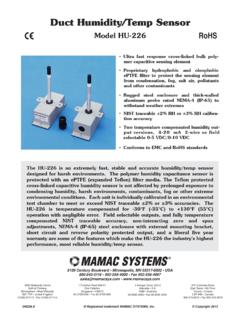
5 RECORDING SW - WARMCOMM - FOR PC UNDER RECORDING PRINTING SW - PRINTER ARCHIV - FOR PC UNDER POTENTIAL-FREE CONTACT FOR ALARM THE INER SWITCHED EXPOSURE LIGHTING A)IN THE DOOR,B)ON THE MEASUREMENT OF UV AND VIS EXPOSURE LIGHTING PHOTOQUANTITIES IN THE TEMPERATURE RANGE FROM -9,9 PROTECTION OF THE PROGRAMME SETTING BY A CHIP SIGNALING OF THE DOOR DOOR :EC - DECLARATION OF CONFORMITY1 GENERAL NOTESThe unit CLIMACELL should be used in applications, in which changing the temperature in a sample in range from 0 C to C andthe relative humidity (RH) from 10 % to 95 % in various time modes is may be used in several ways, so please, read this manual s Cooling incubators CLIMACELL areequipped with a microprocessor control with the following features:1. Fuzzy-logic temperature controller and a thermo-sensor PT humidity control by PID regulator with fuzzy logic and a humidity capacity 4 preset programs P1 to P4, 2 programs P5 and P6 to set containing up to 40 Electronic timer with different time modes, see description of programs (page 10).
6 5. Adjustable fan speed from 10 to 100 % in 10 % - steps. 6. Printing the protocol with real temperature and time values via interface RS 232 Chip card reader to store data P1 - P6 and to record to the memory .8. Foil covered touch buttons for easy programming. 32 digit LCD display, illuminated. All parameters seen at once. To your information, the display is already set up to be used in product ranges coming out in is manufactured of high grade materials with the latest technology and is VXEMHFWHG WR VWULFW QDO WHVWV OHDYLQJ WKH SODQW The inner chamber housing as well as the shelves are made of stainless steel. The coating is water based, gray on top of galvanized zinc coated sheet metal, safe for the AND CHECKA fter unpacking the unit, please, check, whether the unit and its facilities are complete and eventual damage must be immediately reported to the transporting the manipulation in case of lifting the cabinet etc.
7 The cabinet cannot be hold by the rail or door. The cabinets of volumes 404 and 707 should be lifted by means of delivered hooks, the rolls are designed for local moving, not for longer standard delivery consists of the temperature cabinet: two sieves, one chip card SO for setting the safety thermosta three chip cards for storing the set programs hose for connecting the input water hose for connecting the input water (order No.: 0671574), hose for outlet of the waste water (order No.: S461762), distilled water unit (order No. R026721) PUTTING INTO OPERATION CLIMACELL has been designed in accordance with the requirements of EU Directives no. 2006/95/EC and 2004/108/EC and tested individually according to EN 61010 -1. Before the device is put into operation IRU WKH UVW WLPH OHW WKH LQVWDOOHG GHYLFH stand motionless in an operating position for 2 starting the work with this unit please study the instructions for use carefully!
8 Put the material on the device sieves only; never put them on the device bottom!&DUU\LQJ FDSDFLW\ RI WKH RRU ZKHUH WKH unit will be placed, must correspond to the weight of the unit itself plus the weight ofthe maximum charge (see chapter 6 -Technical parameters).7KH XQLW PXVW QRW EH SODFHG RQ D RRU covering, which could cause a danger of UH RU VPRWKHULQJ LQ FDVH RI IDOOLQJ RI KRW objects out of the LQ DPPDEOH H[SORVLYH RU WR[LF VWXII RU materials which could give such stuff off may be inserted into the units!Unit is not designed for warming of units may not be used in an HQYLURQPHQW ZLWK D ULVN RI DPPDEOH or explosive substances (such as anaesthetics) mounting and demounting of the unit s parts may be carried out only after disconnecting the unit from the mains by Instructions for 3pulling the supply cord out of the socket. Installation of the unit is carried out by connecting to the mains and connecting to the water source and the of the electric connections DUH VSHFL HG LQ FKDSWHU - Electricinstallation and other the unit is not used for a longer time, disconnect it from the mains by pulling the connecting cord out of the mains cord must not come into contact with hot parts of the of the heating cabinet, its surroundings and the processed material against inadmissible temperature exceeding is ensured by a protective thermostat corresponding to EN GHYLFHV VWDQG RQ WKH RRU 7KH\ DUH space saving and provided with braked wheels.]]
9 The Cooling incubator must stand RQ D DW RRU RWKHUZLVH WKH GHYLFH RSHUDWLRQ FRXOG EH LQ XHQFHG QHJDWLYHO\ Minimum distance of the rear and side wall of the unit from other objects and walls is 100 mm, from the upper wall it is 400 the upper sheet of the inner chamber out and in must be carried out carefully, there is a danger of cutting the chamber seal through as a consequence of careless CLIMACELL is connected to water supply and drain, place the unit in a room ZLWK LWV RRU VORSLQJ WRZDUGV WKH GUDLQ After the device is installed to the desired place, turn the wheels and apply the brakes on them. The front wheels shall be turned onward and the rear ones backward parallelly to the device sides to stabilize the device as much as possible both onward and regularly the protective thermostat function (see chapter Checking the Protective Thermostat Function in the Service Instructions).If the unit operates with a temperature higher than 70 C, take a special care when opening the door.
10 As there is the set RH kept in the chamber, hot steam is generated, which can cause a scald. The tightness and quality of the hoses connection with the generator body should be run over the device is used in another that VSHFL HG ZD\ WKH SURWHFWLRQ SURYLGHG E\ the device could be LOADS sizeweight [kg]/traytotal weight [kg] AND OTHER CONDITIONSB asic data for connection:Mainsconnection:1x230V/50(60) Hz1x115V/50(60)Hz; (standard types are marked with bold face)0 DLQV YROWDJH XFWXDWLRQ Protection against dangerous contact - class:IExternal circuits isolation: double isolation Type of unit plug: as a standard CEE-7/VII, IEC-83/CH, 16 A/250 V (or another according to the type)Socket protection: 10 A - 32 A (acc. tech. parameters in the Operating instructions of the unit)Protectionaccording to EN 60529:IP 20 Overvoltage category according to(IEC 664 - EN 61010): II in case of pollution degree 2 Fuses on the rear wall of the upper (extension) pieceBlow-out fuse T16A/1500 Ambient conditions: ambient temperature: +5 C to +40 C humidity : 80 % at 31 C maximal altitude: 3000 mInstructions for OFTHE COOLINGINCUBATOR VIEW1.