Transcription of Toggles General Specifications - NKK Switches
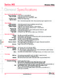
1 Series MRHalf-Inch Diameter Process Sealed RotariesG16 IndicatorsAccessoriesSupplementTactilesK eylocksPushbuttonsIlluminated PBSlidesProgrammableRockersTouchTilt Capacity (Resistive Load) For MRA: 250mA @ 125V AC For MRF or MRK: maximum @ 28V AC/DC maximum (Applicable Range ~ @ 20mV ~ 28V) Note: Find additional explanation of operating range in Supplement section. Other Ratings Contact Resistance: 10 milliohms maximum for MRA; 50 milliohms maximum for MRF & MRK Insulation Resistance: 100 megohms minimum @ 500V DC Dielectric Strength: 1,000V AC minimum for 1 minute minimum for MRA 500V AC minimum for 1 minute minimum for MRF & MRK Mechanical Life: 30,000 operations minimum Electrical Life: 10,000 operations minimum Range of Operating Torque: ~ for MRA.
2 ~ for MRF & MRK Contact Timing: Nonshorting (break-before-make) MRA self-cleaning, sliding contact; MRF & MRK self-cleaning, rotary contactor disk Indexing: 30 Materials & Finishes Shaft: Brass with nickel plating Stopper Plate: Steel with zinc plating for MRA polyamide cover with stopper for MRF Bushing/Housing: Zinc alloy with zinc plating Movable Contacts: Copper with silver plating for MRA; phosphor bronze with gold plating for MRF & MRK End Contacts & Terminals: Brass with silver plating for MRA; phosphor bronze with gold plating for MRF & MRK Common Contacts & Terminals: Brass with silver plating for MRA; phosphor bronze with gold plating for MRF & MRK Base: Diallyl phthalate for MRA.
3 Fiberglass reinforced polyamide for MRF & MRK Environmental Data Operating Temperature Range: 10 C through +70 C (+14 F through +158 F) Humidity: 90 ~ 95% humidity for 96 hours @ 40 C (104 F) Vibration: 10 ~ 55Hz with peak-to-peak amplitude of traversing the frequency range & returning in 1 minute; 3 right angled directions for 2 hours Shock: 50G (490m/s2) acceleration (tested in 3 right angled directions, with 3 shocks in each direction) Sealing: MRK model meets IP67 of IEC60529 standards Installation Mounting Torque.
4 686Nm ( l b i n) Cap Installation Force: ~ ( ~ lbf) for MRA & MRK Processing Soldering Time & Temperature: Wave Soldering for MRA: See Profile A in Supplement section. Wave Soldering for MRF & MRK: See Profile B in Supplement section. Manual Soldering for MRA: See Profile A in Supplement section. Manual Soldering for MRF & MRK: See Profile B in Supplement section. Cleaning: Automated cleaning recommended. Stopper plate, as well as washers for MRA & MRK, must be in place to maintain automated cleaning.
5 See Cleaning Specifications in Supplement section. Standards & Certifications MRA, MRF, & MRK models have not been tested for UL recognition or CSA certification. These Switches are designed for use in a low-voltage, low-current, logic-level circuit. When used as intended in a logic-level circuit, the results do not produce hazardous SpecificationsSeries MRHalf-Inch Diameter Process Sealed RotariesG17 IndicatorsAccessoriesSupplementTactilesK eylocksPushbuttonsIlluminated SizeLow profile body of MRF model accommodates space limitations required for PCB mounting.
6 For the MRA and MRK bushing mount models, the range of behind panel body depths is .323 to .669 ( to ). Positive detent mechanism for distinct feel and audible feedback. Metal bushing and housing construction increases durability. Adjustable stopper plate allows 2 12 position settings. High contact reliability achieved by the self-cleaning contact mechanism. Break-before-make contact timing with sliding contacts in MRA and rotary contactor disk in MRF and MRK models. Interior housing seal and molded-in PC terminals, plus shaft rubber o-ring on MRA and MRK and polyamide cover on MRF model, allow cleaning after automated soldering.
7 MRK model meets IP67 of IEC60529 Specifications (similar to NEMA 4 & 13).Distinctive CharacteristicsSeries MRHalf-Inch Diameter Process Sealed RotariesG18 IndicatorsAccessoriesSupplementTactilesK eylocksPushbuttonsIlluminated PBSlidesProgrammableRockersTouchTilt SWITCH ORDERING EXAMPLEK nobsAPlain BlackBSmall Color TippedCLarge Color Tipped206 DESCRIPTION FOR TYPICAL ORDERING EXAMPLEMRA206-AColorsFor Plain KnobNo CodeBlackFor Color TippedABlackBWhiteCRedEYellowFGreenGBlue HGrayAAShaft Actuated with PC TerminalsACTUATORS & TERMINALS Shaft Terminal MRShaft Actuated
8 WithPlain Black KnobDP with 2-6 Adjustable PositionsPC TerminalsFAActuators & TerminalsAShaft Actuated with PC TerminalsFLow Profile Screwdriver Actuated with PC TerminalsKLow Profile Shaft Actuated with PC TerminalsPoles & Circuits112SP with 2-12 Positions206DP with 2-6 Positions4034P with 2-3 PositionsLow Profile Screwdriver Actuatedwith PC TerminalsKLow Profile Shaft Actuatedwith PC Terminals Slotted for TerminalScrewdriver Shaft Terminal( ) Dia .124( ).031 ( ).039121110911211102 ( ).020 Thk = ( ).
9 010( ).138 ( ).020 Thk = ( ) .010( ).138 ( ).020 Thk = ( ) .010( ).13821C12 1 11 0MR-123456789101112MR-K11221C1 2111 0912 1 11 09( ).394( ).394( ).122( ).090( ).122( ).090 Series MRHalf-Inch Diameter Process Sealed RotariesG19 IndicatorsAccessoriesSupplementTactilesK eylocksPushbuttonsIlluminated of PositionsStopper SettingsNumber of TerminalsSchematicsSPMRA112 MRF112 MRK1122 122 122 122, 3, 4, .. 122, 3, 4, .. 122, 3, 4, .. 121 COM, 12 LOAD1 COM, 12 LOAD1 COM, 12 LOADDPMRA206 MRF206 MRK2062 62 62 62, 3, 4, 5, 62, 3, 4, 5, 62, 3, 4, 5, 62 COM, 12 LOAD2 COM, 12 LOAD2 COM, 12 LOAD 4 PMRA403 MRF403 MRK4032 32 32 32, 32, 32, 34 COM, 12 LOAD4 COM, 12 LOAD4 COM, 12 LOAD POLES & CIRCUITS123456789101112A123456123456AB12 3123123123 ABCDPOSITION SETTING FOR MRA, MRF, & MRK MODELSEach switch is supplied with the stopper set for the maximum number of positions allowed for that model.
10 Prior to installation, the desired position setting should be made. Contact factory for continuous Models1. Remove the protective cover from the switch body. 2. Turn the shaft counterclockwise to the extreme left by using a screwdriver. 3. Inside the cover is a magnifying lens which would be positioned over the number which is to be the maximum position used; when the cover is then snapped into the switch, the projection beside the lens fits into the correct hole for setting the stop. 21C12 1 11 0MR-123456789101112 Protective CoverLensProjectionMRK & MRA Models1.