Transcription of IR Signature Suppression of Modern Naval Ships - …
1 IR Signature Suppression of Modern Naval Ships1J. ThompsonD. Davis Engineering , Ontario, CanadaA. M. BirkDepartment of Mechanical EngineeringQueen s UniversityKingston, Ontario, CanadaABSTRACT:Most Modern Naval Ships include some form of infraredsignature Suppression (IRSS) to reduce the shipsusceptibility to IR guided anti- ship missiles. In some casesthe IRSS may be very basic while in other Ships great carehas been taken in the ship design process to achieve a verylow Signature . The trend in recent years with new shipprograms is towards a more systematic and comprehensiveapproach to previous years it was considered enough for a ship IRsignature specification to consist of a single statement: theship IR Signature shall be minimized.
2 This is no longer goodenough. New ship design programs are including detailed IRsignature management studies that include IR suppressiontradeoff studies, detailed susceptibility analysis and costbenefit analysis. These studies consider the operatingenviron1ment, the ship layout, and the anticipated and more of these studies are including detailed threedimensional computer modeling of ship IR images inrealistic operating environments. These models are allowingthe analysts to study important effects such as solar heatingor reflection, sea surface clutter, flare decoy deployment andother complex processes that could not be considered in anydetail until recently. All of these mean that new Ships arebeing designed with lower signatures and improvedsurvivability.
3 This paper discusses the main contributions to ship IRsignatures and what means are available to reduce oreliminate these signatures. Examples are given to illustratethe benefits and costs of IRSS under different IR Signature OVERVIEW: A ship Signature is made up from two main components:Internally generated, and Externally generated. Internallygenerated Signature sources include rejected heat fromengines and other equipment, exhaust products fromengines, waste air from ventilation systems and heat lossesfrom heated internal spaces. The primary internal IR source results from the mainmachinery onboard any vessel, in particular drive enginesand electrical generators. The magnitude of signaturesproduced by other sources such as heated windows, weaponsystems, and deck mounted machinery is insignificant incomparison if main machinery is not generated sources result from the surfaces of aship absorbing and/or reflecting radiation received from itssurroundings.
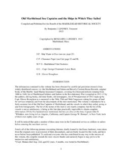
4 The primary sources of background radiationare: the sun, sky radiance, and sea IR Suppression of a ship must consider bothsources. Some argue that there is no point to suppressingthe internally generated sources (plumes, uptakes, hot spots)because it is not possible to suppress the external ignores the fact that there is no solar heating at nightor when the sky is overcast. It also ignores the fact that thesun also generates clutter. With some active measures suchas water wash, the external sources can be taken care of tosome ship MACHINERY:Of all internally generated sources of IR, waste heat andcombustion products from a vessel s main machinery is themost significant. Figure 1 illustrates the ways in which theheat from a ship s machinery can manifest itself in the formof IR types of IR sources, or hot-spots can be identified inFigure 1.
5 First are the warm sections of hull, indicating thelocation of engine compartments on the other side. Heat 1 Presented at ASNE 21st Century CombatantTechnology Symposium, 27-30 January ( m)024681012 CONTRAST RADIANT INTENSITY (kW/ m-sr)Legend10 km4100 m1800 m600 m10 m0 Figure 1 Infrared Image of a Typical Unsuppressed Shipradiating from running machinery heats the air in thesecompartments, that in turn convects to the uninsulated hullof the ship . Next are the funnel spaces, heated by engineroom ventilation air and hot exhaust uptakes runningthrough them. With no insulation installed on funnel walls(as in this case), the funnel exterior is heated much like thesections of ship s the top of the two funnels can be seen the extremely hot(300-400(C typically) exhaust uptake metal.)
6 The relativelylarge area (2-5 m2), high temperature, and location high onthe ship make visible uptake metal the largest singlecontributor to internally generated signatures. Adding to theuptake metal hot-spot are the emissions from hot exhaustgases. A soot-free exhaust plume contains mostly hot CO2gas and water vapor, that radiates in a narrow spectral bandfrom to m. Much of the radiation in this wavebandis quickly absorbed by the atmosphere, but some of thisradiation can penetrate through many km of at ranges of 10 km or more, the plume can still be avery significant contributor to ship IR Signature . Figure 2presents the spectral emission from a typical GE LM2500plume at a number of 2 Spectral Emission of 75 kg/s @ 500(C PlumeThe final hot-spot shown in Figure 1 that is a result of shipmain machinery is the hot communications mast.)
7 The mastand other parts of the ship can be heated by hot plumeimpingement. The mast hot-spot is a concern in instanceswhen a tailwind causes the plume to impinge upon a ship smast. Unsuppressed plumes can heat masts and mountedelectronics to 100-200 (C, resulting in a very large hot-spothigh above the water. The high impingement temperaturesmay also result in failure of the sensitive electronicsmounted on the eliminate, or at the very least minimize the severity of thewarm hull sections and funnel sides requires application ofbasic thermal design. Compartments should be ventilated toa sufficient extent as to keep compartment temperatures atbelow 50(C. Any compartments or funnel spaces that areheated to above ambient should have thermal insulationapplied to all external bulkheads.))
8 Application of even 25mm (1") of glass wool insulation can reduce outer skintemperatures to an acceptable contrast temperature. As aguideline, hull surfaces heated from within should notexceed a contrast temperature of 5(C. Other compartmentsaround the ship that may have temperatures different fromambient should also be considered. Negatively contrastedsurfaces resulting from cool, air conditioned electronics baysfor example are to be avoided as well. The remaining hot-spots (ie. hot uptake metal, plume, plumeimpinged mast) are most effectively treated by suppressingtheir source, the hot exhaust gases from the main Suppression devices provide an optical block, or filmcooling of hot uptake metal, ignoring the importance of hotplume emissions.)
9 Plume cooling is also required, so as toreduce direct IR emissions from the plume, and reduce masttemperatures under impingement situations. Figure 3illustrates four popular IRSS devices in use 3 Popular Engine Exhaust IRSS Devices-3-150200250300350plume exit temperature (oC)0246810device static back pressure (kPa)E/D nozzle exit area changed to affect change in plume of these four devices use a film of cool ambient air tosuppress the visible metal. Resultant metal temperatures aresimilar for all four devices, approximately 20-30(C aboveambient. This is considered to be a sufficient level ofsuppression to protect against today s ability of each device to cool the average plumetemperature varies significantly amongst the four.)
10 Theobjective of the UK cheesegrater is to cool metal not theplume. For this reason the UK device adds little mass flowof cooling air to cool the plume. It should be noted that thecheesgrater requires fans for it to operate and if these fansare turned off, hot gases may enter the funnel spaces. TheUS eductor-BLISS entrains cooling air in its mixing tubeand diffuser section, for both plume and metal cooling. Ina similar way the DAVIS (Canada) eductor/diffuser andDRES-ball both entrain cooling air for metal and plumecooling. It is believed that the more efficient diffuser sectionin the eductor/diffuser and DRES-Ball results in superiorplume cooling. The DAVIS devices have been shown toachieve average plume temperatures of 200-250(C.)