Transcription of MAXI WINDOW INSTALLATION INSTRUCTIONS - …
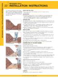
1 On the back of this page you will find a diagram of a MAXIW indow Awning. It will be necessary to refer to thisdiagram while reading these INSTRUCTIONS so that you canproperly install your MAXI WINDOW THE BRACKETSIf you ordered your MAXI Awning wider than the windowcasing, the awning must be installed above the casing toavoid the roller tube from hitting the casing. If the awninghas been ordered the same width as the outside dimensionof the casing, you have the option to install on the casingor the wall above the casing. After determining yourbracket height refer to the diagram on the back of this the MAXI end bracket (#1). Note the direction inwhich the MAXI bracket is installed. The mounting dis-tance from each MAXI end bracket is always the same asthe width ordered. This dimension is taken from theoutside edge of the THE BRACKETSThe bracket must be secured to studs, headers or joist with3/8" diameter lags and a length that will penetrate theframing 2 1/2" to 3".
2 Drill a 1/4" diameter hole 2 1/2" deepinto the framing, square and center into the studs or joistsat each point a lag is being installed. It may be necessaryto drill a 3/8" diameter hole, at each 1/4 hole, the depthof the wood siding or casing to prevent the siding fromsplitting. Then remove the gear or motor from the MAXI bracket and install the brackets at your the width of the awning does not allow you to install thebrackets on studs or joists, a high quality toggle bolt may beused. This style of fastening requires that you have solidsheathing behind the siding in order to support the THE HOODIf an optional hood has been included with your MAXIW indow Awning, it must be installed before installing theroller tube. To locate the hood brackets, snap a chalk line3/4" above the already installed maxi brackets (#1).
3 When2 hood brackets are supplied, position the top of eachbracket even with the chalk line snapped, and in from theends approximately 25% of the length of the hood. When3 or more hood brackets are supplied, position each endMAXI WINDOW INSTALLATION INSTRUCTIONS bracket 2' to 3' in from the ends of the hood. Space anyadditional brackets evenly between the two end all hood brackets to studs or headers. Use 3/8"diameter lags and a length that will penetrate the framing 21/2" to 3" deep. Insert two 5/16" x 1" bolts into the hood (asshown on the diagram) for each hood bracket. Assemblethe hood end covers to the hood. Place the hood (#9) ontothe hood brackets (#10). Adjust the hood side to side sothere is 1/2" between the hood end covers (#11) and theMAXI bracket (#1). Carefully tighten the hood to thebrackets with the nuts and washers THE AWNINGWith the fabric installed on the roller tube and front rail,insert the round pin roller tube end cap (#7) which isattached to the roller tube into the mounting bracket (#1)as shown.
4 Make certain that the front rail is in front of theroller tube. Next, slide the square peg on the roller tube endcap (#6) into the 7:1 worm gear (#8). Attach the gear bypassing the two bolts through the mounting bracket (#1)and thread them into the gear (#8). Pivot the gear so thatthe hand crank eye is slightly angled away from the wall thentighten the bolts securely. The MAXI arms (#3) are designedto be fastened anywhere along the front rail (#4). Whenonly two arms are supplied they are to be mounted in fromeach end no more than 25% of the length of the front additional arms must be spaced evenly between thetwo end arms. To determine the proper mounting height ofthe arms, take the projection of the awning ordered andsubtract 2 1/4". This dimension is the arm mounting heightmeasuring from the bottom of the mounting bracket (#1) tothe location of the bottom of the arm wall bracket.
5 With thearm in its relaxed position, pointing toward the ground, andthe front rail arm end facing in to the center of the awning,position the arm wall bracket above the mark on the walland mark the location of the lag bolts. Install a 5/16"diameter lag by the proper length into the location of thelower hole. Tighten the lag just enough to allow the slot ofthe arm bracket to slip snugly behind the lag. Install thesecond lag into the upper hole of the arm wall this procedure for all arms. Remove the front railend cap (#5) and insert one track bolt per arm into the slotof the front rail (#4). Reinstall the front rail end cap. Swingeach arm up to the front rail and fasten the arm to the trackbolt with the nuts supplied. Level all arms then tighten thenuts WINDOW Awning Parts List1. Maxi End Bracket#_C5232.
6 Maxi Roller Tube#ME5253. Mini Arm Assembly#_A610 - _A6154. Maxi Front Rail#_E6205. Front Rail End Cap#_P6256. Square Pin Roller Tube End Cap#BP5377. Round Pin Roller Tube End Cap#BP5388. 7:1 Ratio Worm Gear#ZA5399. Maxi Hood Profile#_E62910. Maxi Hood Bracket#_E63111. Hood End Cover#_E630 Replace the space proceeding the part # with aW for White, a B for Bronze, or an S for Silver.