Transcription of Geartronics GPI-5 Programmable Gear Position …
1 Geartronics GPI-5 Programmable Gear Position Indicator The gear Position indicator is a universal display unit that can be used with any sequential gearbox with a 3-wire potentiometer (or hall-effect)) barrel Position sensor. Any gear order can be accommodated with up to 7 forward speeds. Programming the unit is achieved by the use of a single button on the bottom of the unit. Wiring Power loom: Red: +12v ignition supply Black: Chassis ground Yellow: Reverse relay output (switches to ground when reverse is selected) Sensor loom: Red: +5v sensor supply Black: Signal ground White: Signal connects to potentiometer wiper The wiring harness and potentiometer are terminated with miniature Sureseal connectors with the following pinout.
2 1 Ground 2 5V supply 3 Signal Programming In order for the display to show the selected gear, the Position of the potentiometer and hence the selector barrel Position must be learned for each gear. This is achieved by entering programme mode by use of the red button, adjacent to the connector on the bottom of the unit. Gently press and hold the button for 3 seconds. The display will flash the repeating sequence P 4 5 6 7 . Momentarily press the button when the display is showing the number of forward gears, not including neutral & reverse.
3 The display will now show R . Select reverse gear and press the button momentarily (this applies even if your gearbox uses a separate lever to engage reverse, as is the case with gearboxes having the 1N23456 gear order). The display will then show N . Select neutral and press the button again. The display will then show 1 . Select first gear and press the button. Continue in this fashion until all gears have been selected. The display will then flash a repeating sequence of P R N B . This allows the function of the relay output to be programmed.
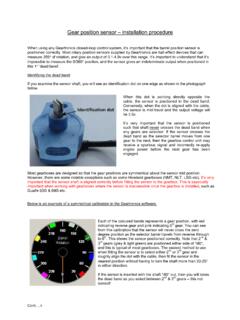
4 This can be configured to give a switched ground output for Reverse, Neutral or Both neutral and reverse. Notes: 1. If the potentiometer is moved or replaced, it may be necessary to repeat the programming routine so that the new gear positions can be learned. 2. Some rotary gearbox potentiometers are only capable of providing an electrical output for approximately 340-350 of rotation. The remaining 10-20 is referred to as the dead band . The centre of the dead band is when the identification mark on the sensor shaft is pointing away from the cable.
5 If possible, the potentiometer should be positioned such that the rotation of the selector barrel does not cause the potentiometer wiper to travel across the dead band. In most instances the shaft can be turned through 180 to achieve this. The programming algorithm is designed to work with the shaft in any Position , but potentiometer wear can be an issue if the wiper repeatedly crosses the dead band. Gear counter The display unit logs the total number of gear-shifts made since the gear positions were programmed, or since the counter was last reset.
6 The counter is maintained even after the ignition is turned off. To access the log, press the button 3 times within a 2 second period. The number of shifts will be indicated on the display in a 4 digit sequence (maximum count 9999). The sequence will repeat until the button is momentarily pressed, upon which the display will revert to its normal function. To reset the counter, press and hold the button for 2 seconds during the count re-call sequence. Display Self Test To check the function of the LED display, press and hold the button during power up.
7 The display will show the characters G E A R T R O N I C S in a repeating sequence until either the power is removed or the button is pressed. Geartronics Ltd. April 2011