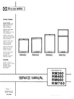
Transcription of Dometic - RVRefrigeratorRepair
1 DometicOS1160A 11/88A-lDometicAES REFRIGERATORDIAGNOSTIC SERVICEMANUALThe Dometic CorporationCorporate Office 2320 Industrial ParkwayElkhart, In. 46515219-295-5228 Warranty 205 E. Fenn LaGrange, In. 46761219-463-2191 Technical services 509 S. Poplar , In. 46761219-463-4858 Diagnostic Service ManualsTABLE OF CONTENTSD iagnostic Flow ChartsNo Operation ..No 120V AC Operation .No 12V DC Operation .No Gas Operation..Operation and DiagnosisDometic AES RefrigeratorsGlossary of Terms ..Continuity Readings forSwitch Card and Harness .Service Bulletins..AES Refrigerator ManualSubscription Form .. * .A-5- 1..A-5-2..A-5-3..A-5-4.. A-6- 1.. A-7- 1.. A-8- 1..A-9- 1.. REFRIGERATORDIAGNOSTIC FLOW CHARTNO OPERATIONC heck supply Polarity2. Battery supply3. Wire sizeCorrect coach wiringas necessary.
2 (see pgs. A-6-23to A-6-30para. 79-84) OKReplace fuse asnecessary(see pg. A-6-34,para. 96) OKCheck OKOKC heckOKReplace thermostatas necessary(see pgs. A-6-34to A-6-35,97- 100) switch asnecessary(see pgs. A-6-35to A-6-36, ; & to A-8-5)Check solenoid asnecessary(see pg. A-6-36,para. 104-106)A-5-1 AES REFRIGERATORDIAGNOSTIC FLOW 120V AC OperationCheck supply Polarity2. Battery supply3. Wire sizeNOTOKC orrect coach wiringto A-6-30, )Correct coach wiringCheck AC voltageand/or power sourceNOT (breakers) as necessary OK(see pgs. A-6-22 toA-6-23, ) AC heating elementReplace heating elementfor proper resistance;w/correct size &Insure proper sizewattage as necessaryand wattageNOT OK(see pgs. A-6-38 toA-6-39, ) switch switchOKCheck solenoidOKNOTOK(see pgs. A-6-35 toA-6-36, & to A-8-5)Replace solenoid asnecessary(see pg.
3 A-6-36,para. 104- 106)Check AC leads onprinted circuit boardNOTC orrect as necessary(seepg. A-6-39,para. 117)OKA-5-2 AES REFRIGERATORDIAGNOSTIC FLOW 12 VOLT DC OPERATIONC heck supply voltage1. Polarity2. Battery supply -Correct coach wiring as necessary(seepgs. A-6-23 to A-6-30,3. Wire sizeNOT OKpara. 79-84) that refrigeratoris wired directly toCorrect wiring as necessary12V battery(see pgs. A-6-27 & A-6-29)NOT OK for proper gauge Rewire w/proper gauge wire aswire in 12V installationnecessary (see chart on pg. A-6-26) 1 Check ignition lockterminal for 12V whenignition key is placed in the ON position only NOTR epair circuit as necessary(seepg. A-6-40,para. 120) DC relayCheck 12V DC element NOT ,Replace relay as necessaryReplace switch as necessary(see pgs.
4 A-6-41 to(see pgs. A-6-35 to A-6-36, 8c pgs. A-8-l toA-6-42, para. 123-l 27)Replace element as necessaryA-8-5)(see pgs. A-6-42 toA-6-43, para. 128-l 29)OK Correct connections and/orreplace printed circuitboard as necessary (see printed circuitboard & connectionstNOT OKA-11-3 to A-11-5)A-5-3 AES REFRIGERATORDIAGNOSTIC FLOW CHARTNO GAS OPERATION1 Check supply voltage1. Polarity2. Battery3. Wire sizet-iCorrect coach wiring asnecessary (see pgs. A-6-23 Not to A-6-30, ) that 120V ACis not presentat receptacleDisconnect supply line(seepg. A-6-44,para. 134) that 12V is notpresent at tag lineRepair circuit asnecessary (see pg. A-6-44,para. 134) coach regulatorCheck gas pressure as necessary (see A-6-44 to A-6-45,OKpara. 135-l 36) flue, clean orreplace burner andorifice as necessary(see pg.
5 A-6-48, 149)(continued on page A-5-5)A-5-4 AES REFRIGERATORDIAGNOSTIC FLOW CHARTNO GAS OPERATION (continued) solenoidNOTOKR eplace solenoid asnecessary (see to A-6-46,para. 137-l 40) ,Check electrode andelectrode wireNOTOKR eplace parts asnecessary and/or(See pg. A-6-47,para. 145- 146)A-5-5 OPERATION AND DIAGNOSISDOMETIC AES REFRIGERATORSA-6- 1(1)Welcome to the Dometic refrigerator training this program we will discuss thefeatures, operating sequences and diagnostic procedures for the Dometic refrigerators that areequipped with the Automatic Energy Selector Control system; for short.(2)With this type of control system the customerno longer has to manually switch therefrigerator to the desired mode of that is left for the customer to do is to turnthe refrigerator ON and to select the desiredtemperature range by way of the thermostatknob.
6 The refrigerator will automatically selectbetween 120V AC, 12V DC or LP gas tooperate the refrigerator.(3)The selection will be made electronically withthe highest priority going to the 12OV AC cooling mode; second priority going to the 12 VDC heating element, providing the motorhome s ignition key is turned ON and thevehicle is in motion. Last priority is LP gasoperation.(4)Since the introduction of the first in 1983 there have been threedistinct model series or generations will discuss each of the three model gener-ations separately to illustrate the parts locationand operational differences between eachmodel (5)Shown here is the RM1303 that is one of the models that make up thefirst generation refrigerators. The models in this series includefrom the smallest size to the largest size: the RM663 which is a 5 cubicfoot refrigerator, the RM763 which is a 6 cubic foot refrigerator andlastly, the RM1303 which is an 8 cubic foot refrigerator.
7 (6)Let s now take a closer look at the partslocation and operation of these models. Fromthe lower front of the refrigerator we can seethe main control panel assembly. Thisassembly contains the two control knobs andthe lamp that will illuminate when therefrigerator is turned on.(7)The knob on the right is the main switch thatis used to turn on the refrigerator and theknob to the left is the thermostat control thatis used to regulate the lower cabinettemperatures within the food zone range. (8)When the unit is turned on, the lampwill illuminate green to let the customer knowthat the refrigerator is turned on and that thesystem has sufficient DC voltage to operate (9)It must be remembered that a DC wire hook-up to the terminal block is required for refrigerator to operate on 120 volts AC,12 volts DC or LP gas.
8 (10)From the rear of our example we can see theshut-off valve and knob where the main LPgas supply is connected to the refrigerator, 12volt DC terminal block where the 12 voltpower source comes into the refrigerator tooperate the system and the LP gas solenoidvalve which includes the 12 millimeter testplug where the LP gas pressure can bechecked.(11)The solenoid valve replaces the user operatedflame failure safety device that is found on themanually controlled refrigerator models.(12)Finally, to the right of the solenoid valve isthe orifice burner assembly which generatesthe heat required on the LP gas mode tooperate the absorption cooling (13)Just above the burner assembly, located in thegenerator section of the cooling unit, are the12 volt DC and 120 volt AC heating elementsthat provide the heat to the cooling unit onthose modes.
9 (14)By removing the two screws on the left side ofthe base assembly and one screw in the burnerarea, rotate the clamping plate clockwise toremove it.(15)The mounting plate assembly can then be moved backward to gain access to the re-maining parts in the control system.(16)From this view we can see the Printed CircuitBoard which controls the automatic heatselection functions of the refrigerator and the12 volt DC relay which energizes the 12 voltDC heating element when the automaticselection calls for 12 volt operation. To theright of the DC relay is the igniter (17)This component replaces the piezo lighterthat has been used on Dometic manuallycontrolled refrigerators for several years. Whenthe automatic controls select LP gas operation,12 volts are sent to the igniter which producea high voltage to create a pulsating spark atthe burner.
10 If for any reason the flame blowsout, the igniter will re-light the flame at theburner.(18)To better understand how the first generationseries models operate, we will illustrate how atypical RV family would use the is always recommended to pre-cool therefrigerator before taking the RV on a trip togain the most efficiency from the unit. So, aday or two before the customer plans to leaveon vacation the coach is plugged into 120 voltsshore power.(19)The customer then selects the desiredthermostat setting on the refrigerator. Anormal setting for the first generation series issetting number 4,which will provide anapproximate lower cabinet temperature rangeof 35 to 40 degrees.(20)Now, when the main rotary switch is turnedon, the refrigerator will automatically startoperating on the 120 volt AC cooling (21)To let the customer know that the switch isproperly turned on and that there is sufficientDC power to energize the system, lampwill illuminate green.