Transcription of Determining Stack Height to Prevent Contaminant …
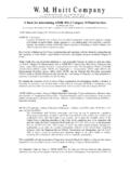
1 AbstractDetermining Stack Height to Prevent Contaminant Re-Entry through Building IntakesClyde J. Porter, PE, CIHAir Science & Engineering, LLCD ayville, CT 06241 Employees at a printing facility were reporting objectionable solvent odors from a process exhaust re-entering through the building HVAC solve the problem, calculations were performed using ASHRAE s revised Stack Height and exhaust-to-intake dilution methods. As a secondary check, a CFD model was developed and intake concentrations determined with the proposed new Stack in results were found between the various methods. The new Stack was installed and the problem was :Solvent Odors from Process Exhaust Re-Entering through HVAC IntakesProcess Exhaust LouverHVAC Intakes (2 of 9)Existing Conditionas Depicted by CFD ModelProcess Exhaust LouverExhaust Pathlines(colored by solvent concentration)WindBuilding Surfaces colored by solvent concentrationProject Goals Specify Stack location, Height and design so that:1.
2 Solvent concentration at any HVAC intake will be below odor threshold, ppm, at worst-case wind conditions. (Wind speed that is exceeded less than 1% of time.)2. Minimize Stack Height to comply with local codes and to maintain building aesthetic Information: Process Exhaust 4,250 scfm with maximum solvent concentration = 100 ppm; temperature ~80 F. HVAC Intakes Nine (9) separate intakes including six (6) side-wall grilles and three (3) horizontal grilles. Location of Proposed Exhaust Stack Approximate centerline of facility where roofs intersect. Worst-case Wind Conditions 27 mph (based on climate data); equivalent to mph at building Height . Stack Parameters Upblast with No-Loss cap; exit velocity ~ 3,000 fpm.
3 Desired Dilution Factor= 100 = Method for Stack Height (2003 ASHRAE Applications Handbook; Ch. 44). Procedure: Location and Height of recirculation zones between specific intake and Stack are determined using formulae; minimum Stack Height to keep plume above each zone is determined graphically; formulae used to account for plume rise and Stack downwash to determine final minimum Stack Height for each intake. Goal: Identify most sensitive intake and critical wind direction; generate first estimate of Stack Dilution Calculation(2003 ASHRAE Applications Handbook; Ch. 44) Procedure: Required dilution factor calculated from Stack concentration and odor threshold; initial Stack Height is assumed; horizontal distance between intake and Stack is determined, charts and interpolation then yield the minimum dilution factor at the critical wind speed; procedure is repeated with different Stack heights until required dilution factor is achieved.
4 Goal: Verify most sensitive intake; estimate intake concentration and refine Stack Fluid Dynamic (CFD) Modeling(Commercially available code) Procedure: Geometry is built to represent building configuration, including intakes and exhausts, and the area surrounding the building; boundary conditions are established including worst-case wind condition; mesh is created and flow solution computed; model output is examined regarding plume dispersion, recirculation zones and computed solvent concentrations at intakes. Goal: Demonstrate cause of existing condition and expected results with proposed solution. Verify predicted intake Exhaust LouverNorthLocations of Intakes and Exhaust150 180 Intake(typical)I1I9I6I7I8I3I4I5I2 ProposedStackLocationNorthExisting Exhaust LouverLocations of Intakes and ExhaustHill25 14 1.
5 Geometric Method - Example Calculations:Intake I5 Assume 1:5 downward spread of plume, ASHRAE ch. hschsc= (per trigonometry)hdownwash= de( Ve/Uh)= hplume rise= 3( ) de(Ve/Uh)= hstack= hsc-hplume rise + hdownwashhstack = + = say 8 Summary of Results (Geometric Method):Similar calculations for all the other intakes (at the appropriate wind direction) showed that the tallest Stack Height needed would be for Intake I5when the wind is from the North Stack diameter = Stack capping factorVe= Stack velocityUH= wind speed at roof height2. Dilution Method - Example Calculations:Intake I5I5X = 71 Assume hs = 8 ; Stack diameter= hs/de=8 = 71/8 = charts and interpolation yields:Dilution at Roof Level = 209 ( ) at critical wind speed = 44 mph.
6 (This wind speed occurs less than 1% of time.)Summary of Results(Dilution Method): 8 Stack produces a dilution factor at I5just greater than design goal of Dr= 200. Wind conditions that could produce a dilution factor close to the design goal would be less than 1% of time. 8 Stack should be analysis performed for all other intakes. Intake I5found to be most sensitive to plume, for given Stack Height , I5had lowest dilution CFD Analysis Model Setup and Example OutputSteady state models were developed for the existing case (with process exhaust through louver on North wall) and for the Stack case at the proposed location and Height 8 above tallest building roof. Models included a wind flow from the North because other analyses showed this wind direction would have the strongest effect on any intake.
7 NorthWindNote: Building Wake Recirculation RegionNote: Roof Recirculation RegionSummary of Results CFD MethodExhaust Pathlines Colored by Solvent ConcentrationOutput shows plume would just touch roof at worst-case wind condition. Note concentration ~ ppm; somewhat higher than expected from Dilution Condition:North Wind at 27 mphSolvent concentration into I5= ppmCFD Results(continued)Model Condition: North Wind at 27 mphPlane cut through Stack reveals vertical and downwind spread of Results Geometric Method produced relatively quick, qualitative results. Dilution Method produced quantitative estimates of Contaminant concentration at the roof level near each intake. CFD produced useful depiction of existing condition, quantitative estimates of Contaminant levels into specific intakes of concern and a helpful depiction of the entire plume.
8 For general applications, Geometric and Dilution Methods may beappropriate. CFD has advantages for cases with different building shapes, obstacles on roof top and nearby buildings. (For critical applications, wind tunnel modeling is currently considered the most accurate analysis method.) 8 Stack was installed. Complaints of solvent odor inside the building were eliminated. Problem resolved. For the proposed Stack location, a minimum Stack Height = 8 above upper roof will Prevent contamination of building intakes. Analysis results were generally consistent between the three methods used, though CFD predicted higher intake concentrations than the Dilution Method.