Transcription of October 13, 2011 - metropolis.com
1 USER GUIDE Metropolis Call Accounting and Telemanagement SL Version METROPOLIS TECHNOLOGIES, INC ii Metropolis Technologies, Inc. and/or Licensed Distributors shall have no liability or responsibility to purchaser or any other person or entity with respect to any liability, loss or damage caused or alleged to be caused directly or indirectly by the Application software, including but not limited to any interruption of service, loss of business or anticipatory profits or consequential damages resulting from the use or operation of the software. Metropolis Technologies reserves the right to change the specifications and operating details of this product without notice. 2015 Metropolis Technologies, Inc. All rights reserved. METROPOLIS TECHNOLOGIES, INC iii Table of Contents SYSTEM 8 FEATURE OVERVIEW .. 9 STATUS INDICATORS (TRAFFIC LIGHTS).. 9 PBX 9 Support 9 CALL VOLUME CALLING Map Redrawing Clearing Map SHORTCUT CABLING.
2 13 SERIAL NULL MODEM CROSSOVER SOFTWARE COMMUNICATIONS PBX Serial Com IP as IP as File Folder Delivery ..16 PBX CONFIGURATION ..17 PBX Live PBX Data ..17 Outgoing Calls Format Tab (Required)..17 Incoming Calls Format Tab (Optional) ..17 Internal Calls Format (Optional)..18 USER GUIDE l METROPOLIS TECHNOLOGIES iv Filters ..18 CDR Filter ..18 Other PBX DATA DISPLAYING PBX CONFIGURING RATES AND Call Classifications ..21 RATE RATE Premium Carrier Rate Per Minute Rate Tables ..22 User Defined Rate Markup and Surcharges ..23 CHARGING INCOMING LEAST COST SPECIAL NUMBER GRACE TAX REGIONAL Local Local Toll Calls ..27 Call Class Over DETERMINING THE COST OF A CREATING ADVANCED Exporting Department Deleting All Entries ..28 DIVISION AND HIERARCHY LEVELS (SL PROFESSIONAL ONLY)..29 ADVANCED Exporting Division Names ..29 Deleting All Entries ..29 CONFIGURING EXTENSIONS ..30 Add ..30 Delete ..30 USER GUIDE l METROPOLIS TECHNOLOGIES v ADVANCED EXTENSION Importing Export Extensions.
3 31 Delete Unknown Extensions ..31 Delete All Extensions ..31 ACCOUNT CODES ..32 ADD ACCOUNT Add Delete Find Code ..32 Leading Zeroes in Account Codes ..32 ADVANCED Export ..32 AUTHORIZATION CODES ..33 CALLER PROFILES ..34 CALLER NAME TELEPHONE NUMBER SMTP EMAIL PBX Alarm Email ..36 Text EMERGENCY CALL Visual Pop up Email ..37 Text TOLL FRAUD Add Toll Fraud CUSTOMIZATION ..39 Process Incoming Charge Incoming Process Free Calls ..39 Process Extension to Extension USER GUIDE l METROPOLIS TECHNOLOGIES vi Mirror and Store Both Sides of Internal Rounding Duration ..40 Rounding COUNTRY MISCELLANEOUS Privacy Masking CUSTOMIZING THE DATABASE Regional Map ..42 Local Enlarged Map ..42 Show Account Show Authorization Show Large Icon MAINTENANCE Reset Maps Shutdown without User Schedule a Regular MISCELLANEOUS Lines per Report Page ..44 Center Password Remove Report Incoming Call Plot No Basic Security.
4 45 Enhanced Security ..46 DATA UTILITIES ..47 PRINTING CALL PAUSE REPROCESSING CDR EXPORT CALL RECORDS TO A TEXT EXITING THE USER GUIDE l METROPOLIS TECHNOLOGIES vii MAINTENANCE ..49 PURGING CALL VIEWING THE EVENT REPORT Report Call Types ..50 Output Delivery SCHEDULED Create a Scheduled Report Schedule Frequency / Repeat Report MEMORIZED Create a Memorized TRAFFICWATCH (SL PROFESSIONAL ONLY)..53 MULTI SITE MULTI SITE MULTI SITE CONFIGURING MULTI SITE FREQUENTLY ASKED METROPOLIS TECHNOLOGIES, INC 8 0 SYSTEM REQUIREMENTS Metropolis telemanagement applications do not require a dedicated PC/Server. Virtual environments, such as VMware may also be used. Please contact the Metropolis Technical Support department for installation. System Requirements Windows XP, Windows Vista, Windows 7, Windows 8, Windows Server 2003, Windows Server 2008, Windows Server 2012 32 bit or 64 bit 2 GB RAM (32 Bit) or 4 GB RAM (64 Bit) 20 GB hard drive space (for raw data retention) Adobe Reader and/or Microsoft Excel (to output reports in those formats) Internet Connection* NOTE: Windows User Account Control would need to be disabled and the application will need administrative permissions to run.
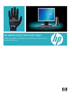
5 These are the minimum requirements necessary to run the telemanagement system. Your operating system/equipment may have additional or higher requirements. Web access functionality requires Windows 7, Windows 8, Windows Server 2008, Windows Server 2012. *Internet connection required for subscription based products and/or for Remote Support access. USER GUIDE l METROPOLIS TECHNOLOGIES 9 1 FEATURE OVERVIEW 24 Status Indicators (Traffic Lights) The software includes a status indicator on the dashboard screen to provide an at a glance view of the system status. A green light indicates that the system is operating optimally, a yellow light indicates a potential problem and a red light signals that there is a problem with the system that needs to be addressed immediately. 77 PBX Indicator If the PBX has not transmitted any call records over the pre configured time period, the PBX indicator light will change to yellow followed by red if the problem is not resolved. Refer to the Alarms section of the user guide for instructions on the configuration of PBX alarm thresholds.
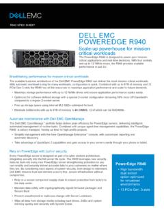
6 78 Support Indicator The Support Indicator reflects the expiration status of the support subscription. A unique support subscription code is required each calendar year in order to update the system with new rate tables, area codes and software upgrades. Green indicates a valid support subscription code, yellow indicates the subscription code will expire within 30 days and red indicates the code has already expired. If the Support Indicator is red, updating with new rate tables without obtaining a new support code will prevent calls from being correctly processed because the system will determine that the updates were obtained without a proper license. USER GUIDE l METROPOLIS TECHNOLOGIES 10 25 Call Volume Graphs The Call Volume Graph can be found in the lower left corner of the main screen and displays the amount of calls by hour, day, week or month. The Call Graph may be used for several purposes: To determine if the system has been processing calls (if not, the call graph for the Day option will be flat).
7 To determine peak call times by selecting Day and viewing the time(s) of day when call volume peaked. To review call activity to find trends for the week (select the Week option). To view call activity, peaks and trends for the month when selecting the Month option. 79 Hour This graph displays call volume during the past hour. The far left edge of the graph indicates call traffic one hour ago and the far right edge indicates current traffic. 80 Day The Day Graph is similar to the Hour Graph and is useful for determining when the majority of calls are made during the current day. 81 Week The Weekly Call Graph indicates the amount of calls that were made during the past seven days and compares the call volume of various days of the week. The x axis indicates the day of the week, while the y axis shows call volume. 82 Month This graph displays the call volume over the past 30 days. The x axis indicates the date (for example, 16 means the 16th of the month) and the y axis shows the call volume for that particular date.
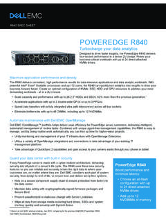
8 USER GUIDE l METROPOLIS TECHNOLOGIES 11 26 Calling Locations World, Regional and Local maps are displayed in the center, lower panel of the main screen. Click on the World, Region or Local tab option to view the corresponding map. Calls are plotted on each map as colored dots corresponding with the department they are assigned. A variety of colors can be assigned to represent different departmental phone call destinations. The color assignments may be changed by the user in the Assign Departments screen. 83 Map Hotspots To get more information on dialed calls to a particular area on a map, click on a dot and select Find Calls to This Hotspot from the menu; a screen will pop up containing the details of each call to the area. 84 Redrawing Maps To redraw call locations on all maps, click on any section of a map. Select Redraw Maps Today from the pop up menu. 85 Clearing Map Plots To erase all call plots from the maps, click on any section of a map and select Clear Maps from the pop up menu.
9 NOTE: To customize the Maps, refer to the Customization section of the user guide. USER GUIDE l METROPOLIS TECHNOLOGIES 12 27 Shortcut Icons The shortcut icons, across the top of the main screen, allow one click button access to frequently used screens. Rates: Select rate tables and set markup rates Special: Set markups for special numbers such as toll free numbers, etc Users: Assign extensions and their correlated department Depts: Assign departments Cost: Display the cost of a call or determine what if charges Reports: Create call reports from one of over two hundred report templates, create graphical reports or schedule reports for automated delivery Dataspy: View the live CDR / SMDR received from the PBX USER GUIDE l METROPOLIS TECHNOLOGIES 13 2 CABLING Cabling is defined here as the process of physically connecting the PBX with the telemanagement computer. To connect the systems: connect one cable from the PBX to the telemanagement PC and another cable from the property management system (if applicable) to the telemanagement PC.
10 A straight through serial cable, with or without a null modem converter or a crossover cable may be used. Usually, cabling is already in place or will be installed by a technician, but for do it yourself users, these topics are discussed below. 28 Serial Cables Serial cables are manufactured with one of two possible connector sizes: DB 25 or DB 9. The DB 25 connector has 25 pins and a DB 9 has 9 pins. DB 25 and DB 9 connectors do not use the same pin configurations to transmit data, as shown in the brief ta ble below. SIGNAL NAME DB 9 PIN # DB 25 PIN # Transmit 3 2 Receive 2 3 Ground 5 7 If the computer in use has a different connector than what is required on the cable, a simple adapter or converter may be purchased from an electronics supply store. The converter is often called a DB 25 to DB 9 adapter and performs the necessary pin translations. Serial cables are usually manufactured as straight through cables meaning that each pin on one end of the cable is directly connected to the corresponding pin on the opposite end.