Transcription of VB14 and VB21 Vacuum Breakers Installation ... - …
1 VB14 and vb21 Vacuum BreakersInstallation and Maintenance InstructionsIM-P019-05ST Issue 20190150/2 Printed in the UK Copyright 2005 IFq 2 PFq 2 QFs RFg SFy TFw UF 2 VB14VB21IM-P019-05 ST Issue 22IF2q 2 2 Safe operation of the unit can only be guaranteed if it is properly installed,commissioned and maintained by a qualified person (see Section 11 of the attachedSupplementary Safety Information) in compliance with the operating instructions. Generalinstallation and safety instructions for pipeline and plant construction, as well as theproper use of tools and safety equipment must also be complied whether closing isolating valves will put any other part of the system or personnelat risk. Dangers might include; isolation of vents and protective devices or alarms. Ensureisolation valves are turned off in a gradual way to avoid system attempting any maintenance consider what is or may have been in the that any pressure is isolated and safely vented to atmospheric pressure beforeattempting to maintain the product, this is easily achieved by fitting Spirax Sarcodepressurisation valves type DV (see separate literature for details).
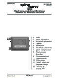
2 Do not assumethat the system is depressurised even when a pressure gauge indicates time for temperature to normalise after isolation to avoid the danger of burns andconsider whether protective clothing (including safety glasses) is product is recyclable. No ecological hazard is anticipated with the disposal of thisproduct providing due care is ST Issue 23 AirconnectionSystemconnectionFig. 1 VB14 Sizes and pipe connectionsVB14 and vb21 " (system connection) screwed BSP or NPT1/8" (air inlet connection) screwed BSP or NPTS ystemconnectionFig. 2 vb21 PF2q 2 2 General descriptionThe VB14 is a small purpose designed Vacuum breaker manufactured in brass for generalpurpose applications on condensing vapour (steam) or liquid systems on pressures up to14 bar g (203 psi g).The vb21 is a small purpose designed Vacuum breaker manufactured in stainless steel for generalpurpose applications on condensing vapour (steam) or liquid systems for pressures up to21 barg (304 psi g).
3 Note: For further information see the following Technical Information Sheet, inAir inIM-P019-05 ST Issue 24 Temperature CPressure bar gSteamsaturationcurveVB14VB21 Steam saturation curveTemperature CPressure bar Pressure / temperature limitsBody design conditionsPN16 PMA Maximum allowable pressure16 bar g @ 180 C(232 psi g @ 356 F )TMA Maximum allowable temperature260 C @ 7 bar g(500 F @ 101 psi g)Minimum allowable temperature-196 C(-321 F)PMOM aximum operating pressure14 bar g(203 psi g)for saturated steam serviceTMO maximum operating temperature260 C @ 7 bar g(500 F @ 101 psi g)Minimum operating temperature0 C(32 F)Designed for a maximum coldhydraulic test pressure of:24 bar g(348 psi g)The product must not be used in this design conditionsPN25 PMA Maximum allowable pressure25 bar g @ 120 C(362 psi g @ 248 F )TMA Maximum allowable temperature400 C @ 13 bar g752 F @ 188 psi g)Minimum allowable temperature-48 C(-54 F)PMOM aximum operating pressure21 bar g(304 psi g)for saturated steam serviceTMO maximum operating temperature400 C @ 13 bar g(752 F @ 188 psi g)Minimum operating temperature0 C(32 F)Designed for a maximum coldhydraulic test pressure of:38 bar g(551 psi g)The product must not be used in this psi gTemperature FPressure psi gTemperature FIM-P019-05 ST Issue 25 Note.
4 Before actioning any Installation observe the 'Safety information' in Section to the Installation and Maintenance Instructions, name-plate and Technical InformationSheet, check that the product is suitable for the intended materials, pressure and temperature and their maximum values. If the maximumoperating limit of the product is lower than that of the system in which it is being fitted,ensure that a safety device is included in the system to prevent the correct Installation situation and the direction of fluid protective covers from all connections and protective film from all name-plates,where appropriate, before Installation on steam or other high temperature install in a vertical position with the system connection of the : As the equipment is to discharge to atmosphere ensure it is to a safe place, the dischargingfluid may be at a temperature of 100 C (212 F).
5 QF2s Vacuum breakerBoiler panAirVacuumbreakerFig. 3 Fig. 4 Air IM-P019-05 ST Issue 26RF2g After Installation or maintenance ensure that the system is fully functioning. Carry out testson any alarms or protective The VB14 and vb21 protect steam plant and process equipment against Vacuum and at the sametime allow condensate to drain effectively from pipework and storage vessels. The valves have aKv of and require a differential pressure of mm Hg to connectionAir inNormal operationThe precision ground stainless steel valve is held firmly on its seatduring normal operating conditions ensuring a tight the point of vacuumAt the point of Vacuum , the valve will instantly lift of its seat. Theair is then drawn in through the upper chamber preventing avacuum being cooling, steam begins to condense resulting in areduction of pressure.
6 The valve remains on its upper seat untilthe pressure in the upper chamber falls below the air inletpressure (usually atmospheric pressure).Air inletIM-P019-05 ST Issue 27 Note: Before actioning any maintenance program observethe 'Safety information' in Section VB14 and vb21 are non-maintainable products. In the event of failure the complete unitshould be There are no spare parts to order a new productExample: 1 off Spirax Sarco " VB14 Vacuum breaker having screwed BSP 2 IM-P019-05 ST Issue 28