Transcription of Hi-Rel HOLD-UP MODULE HUGD-50 : 50W POWER …
1 Hi-Rel HOLD-UP MODULEHUGD-50 : 50W POWER Unique Product for HOLD-UP Solution Reduce Capacitance by 80% High efficiency (98%) POWER range : from 4W to 50W Compatible with 9-36 or 16-40 VDC Converter Include monitoring signals Programmable inrush current limitation RoHS or Leaded process optionGaia Converter Revision M REDEFINING THE SOURCE OF POWER1-GeneralHi-RelGradeFor locations, phone, fax, E-Mail see back coverThe GAIA Converter Hold up deviceHUGD-50 provides a state-of-the-art solution tothe problem of maintaining electronic system inoperation during input bus drop-out for enoughtime.
2 Usually this approach uses very largecapacitors because they are only charged at thevoltage at which POWER fails. The Ga aConverter HUGD-50 MODULE provides an alterna-tive solution to reduce the amount of capacitanceneeded by charging the hold up capacitor at ahigh voltage (typically 38V) while limiting theinput HUGD-50 must be connected between theline source and DC/DC modules. If an EMI filterand /or a pre-regulator are used, the hugd -50is connected between them and the the HUGD-50 charges the externalcapacitor to 38V while powering the DC/DCconverters.
3 If the POWER fails, the hugd -50generates a signal and the converters arepowered from the external capacitor. The HUGD-50 can be used either with 16-40V or 9-36V inputvoltage DC/DC converters since the POWER failvoltage is externally adjustable by the userbetween and .The HUGD-50 features 3 modes of operations: Charging operation mode : when theinput voltage ramps-up and reaches the start-up charge threshold (which is set at 1 Vdc abovethe POWER fail voltage ), the HUGD-50 beginsto charge the external capacitor at 38 VDC whilepowering the dc/dc converter.
4 The chargingcurrent is controlled and externally adjustablebetween 100mA and 2A by a resistor. Thecapacitor charging time depends on the chargingcurrent. When the capacitor voltage reaches 35V,the signal (active low, open-drain) capacitorcharged is activated and the HUGD-50 entersin the normal operation mode. Normal operation mode : in normaloperation mode when the capacitor is chargedand the input bus is between the output powerfail and 40 VDC, the HUGD-50 only consumespower to keep the capacitor charged ( 1W).
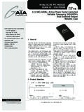
5 The voltage drop between input andoutput is lower than 150mV in the worst case(50W POWER and 9 VDC input voltage) The HUGD-50 will operate indefinitely in this state untilthe input voltage drops below the POWER failvoltage threshold. POWER fail mode : when the input vol-tage drops below the POWER fail voltage threshold, a POWER fail signal is activated andthe HUGD-50 disconnects input from output andconnects the HOLD-UP capacitor to the this point the DC/DC converters are poweredby the capacitor. When its voltage finallydischarges to a value slightly above the powerfail voltage threshold value, a capacitordischarged flag is Solution9-36V & 16-40V DC/DC Converter CompatibleMetallic Case2-Product SelectionOptions :Suffix : /T : option for -55 C start up operating temperaturenothing : RoHS process /S : option for screening and serialization-L : leaded process (available in N.)
6 America) hugd - 50 -option/suffixFor locations, phone, fax, E-Mail see back cover2 HUGD-50 SeriesGaia Converter Revision M 4Hi-RelGrade3- Block DiagramThe HUGD-50 MODULE includes 3 main circuits : an input monitoring circuit an HOLD-UP charger circuit a HOLD-UP monitoring circuit Input monitoring Circuit :The input monitoring circuit monitors the value ofthe input bus voltage and compares it to the powerfail threshold voltage (Vth) set externally through aresistor. Depending on this comparison, the circuitenables the activation of the HOLD-UP switch or thehold-up charger and generates an open-drain powerfail flag (PF).
7 HOLD-UP Charger :The HOLD-UP charger is used to feed the hold-upcapacitor with a constant Vc=38V voltage. The de-sign of this charger has been optimized to minimizethe input inrush current which can be set externallythrough the Vcl input by a resistor. HOLD-UP monitoring Circuit :The HOLD-UP monitoring circuit monitors the chargingstatus of the HOLD-UP circuit generates 2 open-drain flags : the capacitorcharged flag (CC) and the capacitor discharged flag(CD).These flags can be used at system level for powerinterruption management (VME system, PCI.)
8 The following diagram represents the HUGD-50 seriesblock Block DiagramInputMonitoringHold-upMonitoringV iVclVth VoHold-upChargerGiGoVcCCCDPFFor locations, phone, fax, E-Mail see back cover3 HUGD-50 SeriesGaia Converter Revision M 4Hi-RelGrade4- Electrical SpecificationsData are valid at +25 C, unless otherwise or typicalUnitsHUGD-50 InputPermanent input voltage range(Ui)Full temperature rangeFull loadMinimumMaximumVDCVDC940 Transient input voltageFull temperature rangeFull loadMaximumVDC/ms50/100 POWER fail voltage threshold(Vfail)with the settingVth unconnectedMinimumTypicalMaximumVDCVDCVD C1515,315,6 POWER fail voltage threshold(Vfail)with the settingVth connected to groundMinimumTypicalMaximumVDCVDCVDC8,68 ,89 POWER fail hysteresis/TypicalVDC1 Input current consumptionduring charging at 28 Vmin: Vcl unconnectedmax: Vcl connected to groundMinimumMaximumAA0,11,5 Input current consumptionduring charging at 16 Vmin.
9 Vcl unconnectedmax: Vcl connected to groundMinimumMaximumAA0,12,2 OutputOutput powerFull temperature rangeFull loadMaximumW50 Output currentFull temperature rangeUi min. to ,6 Dissipated powerVin @ 9V, full powerMaximumW2 Voltage drop input/ouputVin @ 9V, full powerMaximummV160 Capacitor charged signal (CC)thresholdTurn off thresholdTurn on thresholdTypicalTypicalVDCVDC30,535 Capacitor discharged signal (CD)thresholdwith settingVth unconnectedMinimumMaximumVDCVDC15,916,7 Capacitor discharged signal (CD)thresholdwith settingVth connected to groundMinimumMaximumVDCVDC9,410,2CC, CD, PF sink current/MaximummA25 Admissiblehold-up capacitor/MinimumMaximum F F47030 000 HOLD-UP time at 50W loadVth unconnectedVth connected to groundMinimumMinimum s/ F s/ F11,212,8 HOLD-UP time at 10W loadVth unconnectedVth connected to groundMinimumMinimum s/ F s/ F55,664,4 For locations, phone, fax.
10 E-Mail see back cover4 HUGD-50 SeriesGaia Converter Revision M 4Hi-RelGrade5- Switching Frequency7- Reliability DataParameterConditionsLimit or typicalSpecificationsSwitching frequencyFull temperature rangeUi min. to load to full loadNominal, fixed200 KHz6- IsolationCharacteristicsConditionsTemper atureSpecificationsMean Time Between Failure (MTBF)According to MIL-HDBK-217 FGround fixed (Gf)Case at 40 CCase at 85 C1 500 000 Hrs590 000 HrsAirborne, Inhabited,Cargo (AIC)Case at 40 CCase at 85 C730 000 Hrs300 000 HrsMean Time Between Failure (MTBF)