Transcription of ABOUT WINGLETS by Mark D. Maughmer Over the …
1 ABOUT WINGLETS by Mark D. Maughmer Over the past ten years, from initially being able to do little to improve overall sailplane performance, WINGLETS have developed to such an extent that few gliders leave the factories without them. They are now a familiar sight to nearly every soaring pilot. Few, however, really understand what WINGLETS do. Understanding Drag A winglet s main purpose is to improve performance by reducing drag. To understand how this is done, it is first necessary to understand the distinction between profile drag and induced drag. Profile drag is a consequence of the viscosity, or stickiness, of the air moving along the surface of the airfoil, as well as due to pressure drag (pressure forces acting over the front of a body not being balanced by those acting over its rear).
2 As a wing moves through viscous air, it pulls some of the air along with it, and leaves some of this air in motion. Clearly, it takes energy to set air in motion. The transfer of this energy from the wing to the air is profile drag. Profile drag depends on, among other things, the amount of surface exposed to the air (the wetted area), the shape of the airfoil, and its angle of attack. Profile drag is proportional to the airspeed squared. Readers interested in a more thorough explanation of these concepts are directed to refs. 1 and 2. To measure an airfoil s profile drag in a wind tunnel, a constant-chord wing section is made to span the width of the wind-tunnel test section.
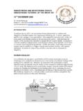
3 In this way, the airflow is not free to come around the wing tips. There is thus no flow in the spanwise direction -- the wing section behaves as if it belonged to a wing of infinite span. Induced drag is the drag that is a consequence of producing lift by a finite wing. If a wing is producing lift, there must be higher pressure on the underside of the wing than on the upper side. Thus, there is a flow around the wingtip from the high-pressure air on the underside of the wing to the low-pressure air on the upper side (fig. 1). In other words, there is spanwise flow on the finite wing that was not present on the infinite wing (fig. 2). This spanwise flow is felt all along the trailing edge as the flow leaving the upper surface moves inward while that on the lower surface moves outward.
4 As these opposing flows meet at the trailing edge, they give rise to a swirling motion that, within a short distance downstream, is concentrated into the two well-known tip vortices. Clearly, the generation of tip vortices requires energy. The transfer of this energy from the wing to the air is induced drag. This process can be idealized as a horseshoe vortex system (fig. 3). As a consequence of producing lift, an equal and opposite reaction must occur -- air must be given a downward velocity, or downwash. With this downwash comes spanwise flow, tip vortices, and induced drag. The goal is to minimize this drag by minimizing the amount of energy used in producing the required downwash -- to reduce the energy that is wasted in creating unnecessary spanwise flow and in the rolling up of the tip vortices.
5 In observing the flowfield around the wing in , it should be clear that the greater the span, the less the tip effect is felt on the inboard portions of the wing. That is, the greater the span, the more two-dimensional like will be the rest of the wing and, consequently, the less its induced drag. As the span approaches infinity, the downwash and induced drag approach zero. Likewise, if the wing is not producing lift, there will be no downwash and thus no induced drag. It is found that the induced drag is a function of the inverse of the square of the airspeed-- it is smallest at high speeds and increases as the aircraft slows down. It also depends on the weight squared divided by the span squared, (W/b)2, how much weight each foot of wing is asked to support.
6 Thus, it increases with the square of the aircraft weight and decreases with the inverse of the span squared. Induced drag also depends on the wing design itself -- how efficiently it produces lift. As a reference point, the most efficient planar wing (a wing with no dihedral or a winglet) is one that has an elliptical loading (greatest at the root and decreasing toward the tip, following the equation of an ellipse). Typical planar wings are slightly less efficient, while non-planar geometries can be somewhat better than the elliptical case. Controlling Induced Drag It has been known for over a century that an endplate at the tip of a finite wing can reduce spanwise flow and induced drag.
7 Unfortunately, to be effective at this, the endplate must be so large that the increase in skin friction drag due to excessive wetted area far outweighs the reduction in induced drag. A winglet provides a way to do Rather than being a simple fence, it carries an aerodynamic load. The idea is to produce a flowfield that interacts with that of the main wing to reduce the amount of spanwise flow. That is, the spanwise induced velocities from the winglet oppose and thereby cancel those generated by the main wing. This effect has been measured experimentally (Fig. 4). Here it is observed that the spanwise flow has been largely eliminated by the presence of the winglet.
8 In essence, the winglet diffuses or spreads out the influence of the tip vortex such that the downwash, and thereby the induced drag, is reduced. In this way, the winglet acts like an endplate in reducing the spanwise flow but, by carrying the proper aerodynamic loading, it accomplishes this with much less wetted area. Nevertheless, recalling the penalty of profile drag with increasing airspeeds, the designer s goal is to gain the most reduction in induced drag for the smallest increase in profile drag. The Winglet Design Process My involvement began over a decade ago when I was asked by Peter Masak to help in the design of WINGLETS for the then-current crop of 15-meter racing sailplanes.
9 Early design procedures were based on the idea of a crossover point -- a breakeven airspeed below which WINGLETS improves performance by reducing induced drag and above which their extra wetted area adds enough profile drag that performance is lower. Our first successful WINGLETS for sailplanes were guided by this notion. A trial-and-error approach was employed that eventually led to some significant In 1989, one of these designs was adopted by Schempp-Hirth as the factory winglet for the Ventus. In retrospect, with the understanding that has come since, it seems that this process, while systematic and logical, was accompanied with a great deal of luck.
10 It now seems somewhat remarkable that with the tool then at hand, we were able to come up with a design that worked so well. In spite of some success, I was somewhat frustrated by the lack of tools then available to analyze or design WINGLETS . Thus, along with a succession of excellent students, a research effort was begun at Penn State to better this situation. In 1994, a collaborative research arrangement with M&H Soaring (Monty Sullivan and Heinz Weissenbueller) in Elmira, New York was begun. Their close proximity to Penn State, along with their acceptance that it would not be a trivial matter to fabricate and flight test the number of trials needed to develop and validate sound design methods, resulted in a fruitful and enjoyable cooperation that continues still.