Transcription of Technical Information Omnigrad S TR66 - Endress
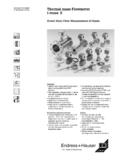
1 Technical Information Omnigrad S tr66 . Modular RTD assembly, flameproof Bar stock-thermowell, with thread or flange Application Heavy duty applications Oil & Gas processing industry Measuring range: C ( F). Static pressure range up to 500 bar (7250 PSI). Protection class: up to IP 68. Head transmitters All Endress +Hauser transmitters are available with enhanced accuracy, reliability and cost effectiveness compared to directly wired sensors. Easy customizing by choosing one of the following outputs and protocols: Analog output mA. HART . PROFIBUS PA. FOUNDATION Fieldbus . Your benefits High flexibility based on modular assembly with a terminal head and customized immersion length Extension neck for head transmitter heat protection Types of protection for use in hazardous locations: Flameproof (Ex d).
2 Intrinsic Safety (Ex ia). Non-Sparking (Ex nA). Dust ignition proof (protection by enclosure). 4 0. TI284T/02/en 71078770. tr66 . Function and system design Measuring principle The Resistance Temperature Detector (RTD) element consists of an electrical resistance with a value of 100 . at 0 C (32 F). It is commonly known as Pt100 and is in compliance with IEC 60751. This resistance value increases at higher temperatures according to the characteristics of the resistor material (platinum). These kind of sensors are called Positive Temperature Coefficient elements (PTC). The coefficient is fixed with = C-1, calculated between 0 and 100 C (32 and 212 F), according to ITS90 (International Temperature Scale 1990). Wire wound platinum resistance thermometers (WW) consist of hair thin highly purified platinum wire double wound inside a ceramic carrier.
3 This is then sealed top and bottom with a ceramic protective layer. The measurements achieved by these resistance thermometers are not only very reproducible, but also have long term resistance/temperature characteristic stability within temperature ranges up to 600 C (1112 F). This sensor type is relatively large in its dimensions and is also not very resistant to vibration. Thin film platinum resistance thermometers (TF) consist of an precise amount of platinum which is vaporized under vacuum onto a ceramic substrate to a thickness of 1 m. This is then protected by a glass layer. The advantages are: smaller dimensions than wire wound and greatly improved vibration resistance. Thin film resistances (TF) are flat, microscopic versions of the wire wound types (WW) with a measurement relevant difference: The temperature expansion behavior of the different layers of this structure leads to minimal mechanical stresses.
4 Temperature changes in thin film resistances (TF) cause the desired temperature relevant changes of the resistor as well as minimal tension stress related resistance changes. Through this the resistance/. temperature characteristic of most thin film platinum resistance thermometers (TF) differs considerably from the standard characteristics at higher temperatures. Thin film resistances are therefore used for temperature measurement in ranges below 500 C (932 F). Measuring system a0010191. Example of an application of the thermometer A Built-in RTD assembly tr66 with head transmitter B RIA 261 Field display The display measures an analog measurement signal and indicates this on the display. The display is connected in a 4 to 20 mA current loop and also derives its supply from the loop.
5 The volt drop is almost negligible (< V). The dynamic internal resistance (load) makes sure that independently from the loop current, the maximum volt drop is never exceeded. The analog signal at the input is digitalized, analyzed, and shown in the rear illuminated display. For details see Technical Information (see "Documentation"). C Active barrier RN221N. The RN221N active barrier (24 V DC, 30 mA) has an galvanically isolated output for supplying voltage to loop powered transmitters. The power supply has a wide-range input for mains power, 20 to 250 V DC/AC, 50/60 Hz to be used in any electrical circuit. For details see Technical Information (see "Documentation"). 2 Endress +Hauser tr66 . Equipment architecture a0010220.
6 Equipment architecture of the Omnigrad S tr66 . 1 Insert TPR100 with 3 mm ( in) or 6 mm ( in) N Extension neck length with mounted head transmitter, for example. For applications in non-hazardous areas 2 Insert TPR300 with 3 mm ( in) or 6 mm ( in) T Thermowell lag with mounted ceramic terminal block, for example. For applications in hazardous areas 3 Terminal head U Immersion length 4 Extension neck A Thermowell length (= U + T). 5 Thread or flange as process connection IL Insertion length = U + T + N + 41 mm ( in). 6 Thermowell from bar stock material The Omnigrad S tr66 RTD assemblies are modularly constructed. The terminal head serves as a connection module for the extension neck to the thermowell in the process as well as for the mechanical and electrical connection of the measuring insert.
7 The actual RTD sensor element is fitted in and mechanically protected within the insert. The insert can be exchanged and calibrated even during the process. Either ceramic terminal blocks or transmitters can be fitted to the internal base washer. Where required, threads or flanges can be fixed onto the thermowell. Measurement range -200 .. 600 C ( F) according to IEC 60751. Performance characteristics Operating conditions Ambient temperature Terminal head Temperature in C ( F). Without mounted head transmitter Housing, material aluminum -40 to 100 C (-40 to 212 F). With mounted head transmitter -40 to 85 C (-40 to 185 F). Endress +Hauser 3. tr66 . Process pressure The pressure values to which the thermowell can be subjected at the various temperatures are illustrated by the figures below.
8 A0010219-en Maximum permitted process pressure for thermowell A Thermowell with D1 = 30 mm ( in). B Thermowell with D1 = 35 mm ( in). P Process pressure T Process temperature Process pressure for thermowell (A) Q1 20 mm ( in). is valid for the following thermowell Q2 14 mm ( in). dimensions: Df 7 mm ( in). max. flow rate = 15 m/s (49 ft/s) for immersion depth U = 200 mm ( in). Process pressure for thermowell (B) Q1 25 mm ( in). is valid for for the following thermo- Q2 18 mm ( in). well dimensions: Df 7 mm ( in). max flow rate = 20 m/s ( ft/s) for immersion depth U = 200 mm ( in). ! Note! Descriptions of the thermowell dimensions Q1, Q2, Df and U see Page 9. Shock and vibration resistance 4g / 2 to 150 Hz as per IEC 60068-2-6.
9 4 Endress +Hauser tr66 . Accuracy RTD corresponding to IEC 60751. Class max. Tolerances Temperature range Characteristics ( C). RTD max. error type TF - range: -50 to +400 C. (Cl. A) |t|1) -50 C to +250 C. Max. deviation ( C). |t|1) 0 C to +150 C. (1/3 Cl. B). (Cl. B) |t|1) -50 C to +400 C. -200 -100 0 100 200 300 400 500 600 C. RTD max. error type WW - range: -200 to +600 C. - (Cl. A) |t|1) -200 C to +600 C - |t|1) 0 C to +250 C. (1/3 Cl. B). - (Cl. B) |t|1) -200 C to +600 C. - - - Max. deviation ( C). a0008588-en 1) |t| = absolute value C. ! Note! For measurement errors in F, calculate using equations above in C, then multiply the outcome by Response time Tests in water at m/s ( ft/s), according to IEC 60751; 10 K temperature step changes: RTD insert Response time 6 mm ( in) t50 s t90 s 3 mm t50 s ( in) t90 s !
10 Note! Response time for the RTD insert without transmitter. Insulation resistance Insulation resistance 100 M at ambient temperature. Insulation resistance between each terminal and the sheath is tested with a voltage of 100 V DC. Self heating RTD elements are not self-powered and require a small current be passed through the device to provide a voltage that can be measured. Self-heating is the rise of temperature within the element itself, caused by the current flowing through the element. This self-heating appears as a measurement error and is affected by the thermal conductivity and velocity of the process being measured; it is negligible when an Endress +Hauser iTEMP temperature transmitter is connected. Endress +Hauser 5.