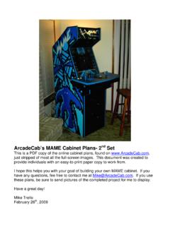
Transcription of The Black Widow - A Portable 15 Meter Beam - …
1 By Allen Baker, KG4 JJH. The Black Widow . A Portable 15 Meter Beam Looking for a Portable 15- Meter antenna for camping or Field Day? Four fishing poles, 50 feet of wire, a few pieces of wood, some PVC and a painter's pole make a stinging Portable performer. The Lure Since the Black Widow uses insulated desired frequency and L is the length be- There are a lot of excellent antenna wire (and MoxGen is based on bare wire), fore trimming. The final dimensions are designs available to the amateur, but few the final dimensions will change due to A = , B = , C = and can combine light weight and portability the insulation's effect on the wire's ve- D = . For an antenna centered in the with the significant gain and front-to- locity factor. middle of the 15- Meter band: A = , back ratio (F/B) of the Moxon Rectangle.
2 I first built the antenna to the wire B = , C = and D = . All the materials necessary for building lengths in the EZNEC model: A = , B = , C = and D = , Construction this Portable antenna (including the mast). are available from your local Wal-Mart, which resulted in an actual resonant fre- Figure 2 presents an overview of an- Home Depot and RadioShack for under quency of MHz. I trimmed the tenna assembly. All of the necessary ma- $125. wires to a final length = FM/FD L, where terials are listed in table 1 along with FM is the measured frequency, FD is the sources for each. The antenna can be The Moxon Rectangle The Moxon Rectangle is a two- element beam with considerable gain, high F/B ratio, and a direct match to 50. coax. [The Moxon-type antenna is named for its originator, L.]
3 A. Moxon, G6XN. Ed.] The antenna is a derivative of the Moxon Square and it has been fur- ther optimized by L. B. Cebik, Figure 1 shows the basic dimensions of the antenna. I used the program MoxGen2 to gen- erate a model at MHz for use with PSK and then fine-tuned it with 1. Notes appear on page 00. Figure 1 The basic dimensions of the Moxon Rectangle. May 2003 1. table 1. Materials List for the Black Widow Antenna Item Qty Description Source Price Item Qty Description Source Price Each ($) Each ($). 1 4 each Crappie Master Fishing Wal-Mart 10 1 each Painter Pole, Mr. LongArm Home Depot Pole, RCM-10LW, 3 sections, 10 ft Model 2324. 2 1 roll 20 AWG insulated RadioShack 11 1 each PVC coupling, 1 Home Depot stranded wire, 75 ft 278-1219 12 1 each CPVC pipe, 10 ft Home Depot 3 1 each Terminal strip, 8-position RadioShack 13 1 each CPVC drop ear 90 elbow, Home Depot 274-678.
4 4 1 each Connector, SO-239 RadioShack 14 1 each CPVC 90 elbow, Home Depot 278-201 15 10 each Sheet metal screw, Home Depot 5 1 pkg Soldering ring, #6 RadioShack self-drilling, #6 . 64-3030A 16 230 ft Nylon twine, #36 Home Depot 6 1 each Epoxy, quick set Home Depot 17 3 each Clothesline tightener, Wal-Mart 7 4 each Screw hook, Home Depot Lehigh 7097. wire diameter 18 50 ft Nylon rope, 3/16 Wal-Mart 8 1 each Wood, poplar, 19 1 each 2 4 8 , pine Home Depot 6 36 Home Depot 20 2 each L-bracket, 3 3 Home Depot 9 2 pkg Three piece extension pole, Home Depot 21 ft RG-8X coaxial cable RadioShack Linzer RP503 278-1313 or per ft equiv Figure 2 Overview of the antenna and its components. Circled numbers refer to materials in table 1. Figure 3 The center hub (left).
5 Note the glued-in (epoxy). threaded sockets for the spreaders. The completed hub (right) shows the mounting stub extending upward and the feed line support extending to the lower left. 2 May 2003 . Figure 4 One of the two insulators for the wire elements. Figure 5 The mounted terminal strip on the feeder arm. Figure 6 A view of the antenna mast support bracket. fashioned from the explanations con- poplar wood to minimize weight. Cut the tained here; however, detailed construc- pieces on a table saw and glue them to- tion drawings for the antenna and the mast gether with yellow wood glue. Cut two of components are available at www. the plastic extension-pole handle sockets cutting screw to attach the element ends a r r l . o rg / fi l e s / q s t - b i n a r i e s / b l a c k - in half so that two threaded sockets are to the insulators.
6 Include the diameter of produced from each. Drill 1 diameter the solder rings when spacing the holes holes in the hub, and epoxy the sockets into Spreaders in the insulators. A view of each of the each hole. I chose to permanently attach insulators can be seen in Figure 4. Modify each of the four fishing poles the mast mount (which is a wooden exten- as follows. Unscrew the handle cap, sion pole threaded on one end) by drilling Wire roughen two inches of the inside surface a hole through the top and bottom Cut wires to the following dimensions with sandpaper, and epoxy a 12 wooden and securing it with epoxy. Extend the non- (including for each loop of wire extension pole (threaded on both ends) into threaded end through the hub and trim off around a screw hook): the fishing pole handle.
7 The original pole the excess after the glue sets. is too flexible and does not exert enough Drill a hole for mounting the Two each, Driven Element = A +. tension to keep the wires tight, so a por- SO-239 connector on one side of the hub. B + 1 Loop tion of the small end must be removed. Drill and mount the CPVC drop ear elbow = + + = . Extend the pole to its full length, and trim on the opposite side, and drill a or . the small end so that the total length from hole through the drop ear elbow into the One each, Reflector Element = A + 2D. handle to tip (including the wooden pole) hub. Sand and paint the hub the same as + 2 Loops is . Use a hacksaw or band saw to the fishing pole handles. Figure 3 shows a = + 72 + = . keep the fiberglass from cracking.
8 Epoxy completed hub. or . a screw hook into the end of the pole. Mark the corners (Figure 1, dimension (Note: If the screw hook diameter is too Insulators intersections A-B and A-D) on the wires large to fit into the end of the pole, cut The ends of the antenna elements using a permanent marker. Strip in- another to 1 off of the pole until it (within dimension C of Figure 1) are sup- sulation from the wire ends at the feed fits. Make all four poles the same length.) ported by a pair of insulators that main- point for the driven element. Attach sol- Spray paint the bare wood with Krylon tain a fixed distance between the wire der rings at the ends that will attach to Ultra-Flat Black spray paint, and when dry ends. The insulators are made from 6 the insulators.
9 Apply two coats of clear lacquer. pieces of scrap CPVC pipe cut in half lengthwise. Six holes are Feed Point and Feed Line Support Center Hub drilled into the PVC insulators to reduce Coax is carried to the feed point of the The center hub is made from thick weight. Drill a small hole for a #6 thread- driven element from an SO-239 connec- May 2003 3. tor on the hub, through the hub, and through an L made of CPVC pipe. The horizontal pipe length is , and the vertical length is 24 . These lengths were determined with the antenna wires in- stalled and the terminal block floating from its vertical support. To account for construction differences, cut the pipe pieces slightly long and trim them in small increments. Connect the coax to the SO-239 con- Figure 7 The erected nector first, then feed the coax through antenna.
10 In the the hub, the drop ear elbow, the horizon- air, the antenna tal pipe, the 90 elbow, the vertical pipe, resembles a and out of a hole drilled in the pipe just Black spider with its legs above where the terminal block will be hanging down. mounted. Cut two terminals free from the strip. Clamp the driven element's feed point wire ends into each side of the terminal block. Then loop the wire around the open hooks at the corners using the per- manent marker lines as an aid. Attach the wires to the insulators. Dry fit all pipe pieces until the terminal strip can be mounted to the lower end of the vertical pipe such that the driven element is straight and parallel to the reflector. At- tach the two-terminal block with a small sheet metal screw.