Transcription of Fundamentals of Multipath Ultrasonic flow meters …
1 Fundamentals of Multipath Ultrasonic flow meters for Gas Measurement Overview of selection, installation, operation and maintenance of wetted-sensor Ultrasonic flow meters Dan Hackett Daniel Measurement and Control, Inc. 11100 Brittmoore Park Drive Houston, Texas 77041 ABSTRACT This paper discusses fundamental principles of Ultrasonic gas flow meters used for measurement of natural gas. A review of an Ultrasonic meter s operation and the equations used to determine actual volumetric flow is presented. The Ultrasonic flow meter s diagnostic capability will also be briefly presented. Further, diagnostic data, in conjunction with gas composition, pressure and temperature, will be reviewed to show how this technology provides diagnostic benefits beyond that of other primary measurement devices. The basic requirements for obtaining good meter performance, when installed in the field, will be reviewed.
2 Most of this information can be generalized to other manufacturer s transit time Ultrasonic flow meters however, these examples provided, particularly with respect to some diagnostic features, are based on the Daniel SeniorSonic Ultrasonic flow meter. INTRODUCTION During the past decade the use of Ultrasonic flow meters for natural gas custody transfer measurement has grown significantly as end users come to understand and accept the technology. Many end users are also utilizing the technology to validate other measurements within a metering system, particularly gas composition and temperature measurement. The publication of AGA Report No. 9, Measurement of Gas by Multipath Ultrasonic meters , 2nd edition in April 2007 and ISO 17089, Measurement of fluid flow in closed conduits - Ultrasonic meters for gas, Part 1: meters for custody transfer and allocation measurement in 2009 has greatly accelerated the installation of Ultrasonic flow meters worldwide.
3 Today virtually every gas transmission company is using this technology, either for fiscal, or for operational applications. There are many reasons why Ultrasonic metering is gaining such broad acceptance in a traditionally conservative industry. Some of the benefits of this technology include the following: Accuracy: Can be calibrated to < , little or no drift. Large Turndown: Typically 50:1, or more. Naturally Bi-directional: Measures volumes in both directions with comparable performance. Tolerant of Wet Gas: Important for production applications. Non-Intrusive: No pressure drop. Low Maintenance: No moving parts mean reduced maintenance. Fault Tolerance: meters remain relatively accurate even if sensor(s) should fail. Integral Diagnostics: Data for determining both a meter s health and dynamic online performance is readily available.
4 It is clear that there are many benefits to using Ultrasonic flow meters . Although the first several benefits are important, the most significant often turns out to be the ability to diagnose the meter s dynamic online performance. The primary purpose of this paper is to discuss basic gas Ultrasonic meter operation, present the basics of diagnostic information, and review installation considerations to assure best meter performance. Ultrasonic METER BASICS Before looking at the main topic of integral diagnostics, it is important to review the basics of Ultrasonic transit time flow measurement. In order to diagnose any device, a relatively thorough understanding is generally required. In today s world of increasingly complex devices, and productivity demands on everyone, companies rely on a well trained work force and instruments that are increasing capable of self-diagnostics.
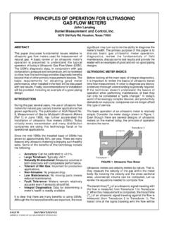
5 Without a good grounding in the basics, understanding diagnostic messages can be confusing. Fortunately for everyone, the basic operation of an Ultrasonic meter is relatively simple. Consider the meter design shown in Figure 1. Even though there are several designs of Ultrasonic meters on the market today, the principle of operation remains the same. Figure 1 - Ultrasonic flow meter Ultrasonic meters are velocity meters by nature. That is, they measure the velocity of the gas within the meter body. By knowing the velocity and the cross-sectional area, uncorrected volume can be computed. Let us review the equations needed to compute flow. The transit time (T12) of an Ultrasonic signal traveling with the flow is measured from Transducer 1 to Transducer 2. When this measurement is completed, the transit time (T21) of an Ultrasonic signal traveling against the flow is measured (from Transducer 2 to Transducer 1).
6 The transit time of the signal traveling with the flow will be less than that of the signal traveling against the flow due to the velocity of the gas within the meter. Let s review the basic equations needed to compute volume. Assume L and X are the direct and lateral (along the pipe axis and in the flowing gas), distances between the two transducers, C is the Speed of Sound of the gas, V the gas velocity, and T12 and T21 are transit times in each direction. The following two equations would then apply for each path: and Solving for gas velocity yields the following: Solving for the speed of sound (C) in the meter yields the following equation: Thus, by measuring dimensions X & L and transit times T12 & T21, we can compute the gas velocity and the speed of sound (SOS) along each path. The speed of sound for each path will be discussed later and shown to be a very useful parameter in verifying good overall meter performance.
7 The average transit time, with no gas flowing, is a function of meter size and the speed of sound through the gas (pressure, temperature and gas composition). Consider a 12-inch meter for this example. Typical transit times, in each direction, are on the order of one millisecond (and equal) when there is no flow. The difference in transit time during periods of flow, however, is significantly less, and is on the order of several nanoseconds (at low flow rates). Thus, accurate measurement of the transit times is critical if an Ultrasonic meter is to meet performance criteria established in AGA Report No. 9. It is interesting to note in Equation (3) that gas velocity is independent of speed of sound, and to compute speed of sound (Equation (4)), gas velocity is not required. This is true because the transit time measurements T12 and T21 are measured within a few milliseconds of each other, and gas composition does not change significantly during this time.
8 Also, note the simplicity of Equations (3) and (4). Observe that only the dimensions X and L, and the transit times T12 and T21 are required to yield both the gas velocity and speed of sound along a path. These equations look relatively simple, and they are; the primary difference between computing gas velocity and speed of sound is the difference in transit times is used for computing velocity, where as the sum of the transit times is used for computing speed of sound. Unfortunately, determining the correct flow rate within the meter is a bit more difficult than it appears. The velocity shown in Equation (3) refers to the velocity of each individual path. The velocity needed for computing volume flow rate, also known as bulk mean velocity, is the average gas velocity across the meter s area. In the pipeline, gas velocity profiles are not always uniform, and often there is some swirl and asymmetrical flow profile within the meter.
9 This makes computing the average velocity a bit more challenging. Meter manufactures have differing methodologies for computing this average velocity. Some derive the answer by using proprietary algorithms. Others rely on a design that does not require hidden computations. Regardless of how the meter determines the bulk average velocity, the following equation is used to compute the uncorrected flow rate. Q V * A (5) This output (Q) is actually a flow rate based on volume-per-hour, and is used to provide input to the flow computer. A is the cross-sectional area of the meter. In summary, some key points to keep in mind about the operation of an Ultrasonic meter are: The measurement of transit time, both upstream and downstream, is the primary function of the electronics.
10 All path velocities are averaged to provide a bulk mean velocity that is used to compute the meter s output (Q). Because the electronics can determine which transit time is longer (T21 or T12), the meter can determine direction of flow. Speed of sound is computed from the same measurements as gas velocity (the X dimension is not required). Transit time is the most significant aspect of the meter s operation, and all other inputs to determine gas velocity and speed of sound are essentially fixed geometric (programmed) constants. INTEGRAL DIAGNOSTICS One of the principal attributes of modern Ultrasonic meters is their ability to monitor their own health, and to diagnose any problems that may occur. Multipath meters are unique in this regard, as they can compare certain measurements between different paths, as well as checking each path individually.