Transcription of LS600 Liquid Level Float Switch Installation …
1 TEL: (631) 293-8450 FAX: (631) 293-8533 WEBSITE: TECHNICAL SUPPORT1 (800) 209-7858 COPYRIGHT 2010 PNEUMERCATOR CO., 1 of 9 Bulletin 193 Rev. C (04/09/10) Liquid Level Control SystemsPNEUMERCATORI nstallation For Model Series: LS600 , LS600M and LS600 WLS600 Liquid Level Float SwitchInstallation InstructionsPC1000LC2000LC1000 For use with thefollowing consoles:TMS3000 TMS20004/9/2013 1:14:20 PM, 1:1, COPYRIGHT 2013 PNEUMERCATOR COMPANY, 2 of 9 Bulletin 193 Rev. C (04/09/10)20"16"12"10"DCBAAB C D1 NOSL * Single Float catalog lengths for 2" NPT STANDARD TANK MOUNT shown in table above. Multiple or single Float custom sizes for RISER OR STANDARD TANK MOUNT maybe specified by customer. Note that "S1" is closest to the bottom for multiple point switches.
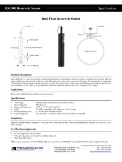
2 ** Optional 150-pound mounting flange (not shown) is available upon " NPT THREADED OPENINGMAX. DIA. "DCBA3" RETAINING CLIP2 REQ'D PER FLOATLIFT GUIDESLADDITIONAL LIFT GUIDE FORUNITS WHERE SENSINGLENGTH "SL" EXCEEDS 18"2" REF(3" REF WHENFLOAT ISLIFTED UP)5" 1/2" OR FLOATMAX. DIA. " RETAINING CLIP2 REQ'D PER OR OR OR BRASSFITTING(2) 2' LONG(10' FOR MODELS w/o HOUSING)18 AWG WIRE LEADS PERFLOAT Switch . SEE COLORCODE TABLE ON PAGE 7 WIRE LEADS(SAME AS FIG. 1)ADDITIONALFLOATS FORCUSTOM OR BRASS SHAFTMAX. LENGTH 192" 144" BRASSSEAL TESTLEVERBUSHING **(2" NPT)FIGURE 2(HOUSING AVAILABLE;SEE FIG. 1)FIGURE 1 BUNA-N " OR BRASS SHAFTMAX. LENGTH 192" 144" BRASSBUSHING **(2" NPT)NIPPLEHOUSING3" " " "REF1/2" WALL OFTANK BOTTOMLLS *5/8" THREADENGAGEMENTS *5/8" THREADENGAGEMENTPRODUCT DESCRIPTION: The LS600 Liquid Level Float Switch consists of (3) model series as shownin the table below.
3 All model series are supplied with minimum (1), up to (4) floats (contact factory for morefloats) for Liquid Level sensing. If ordered by customer, manual test lever is installed on top Float . ModelLS600M has miniature Float (s) for Installation into 1" NPT minimum tank opening and applications with veryclose distances between set points that cannot be achieved using the standard LS600 . The LS600W units aresupplied with interface Float (s) designed to sense levels between two immiscible liquids, typically used in anoil/water separator tank. Units can be designed to automatically detect field wiring faults when used withPneumercator's TMS series controller FAULT-DETECT supervised wiring " SEPARATE OUTLINE DRAWING 1062021"17"13"11"7 1/4" 9 1/4" 13 1/4" 17 1/4"216"12"8"6" LS600 MODELSERIESLS600 MYESNOLS600W20"16"12"10"1 NOMANUALTEST LEVERSTANDARD SHAFTLENGTH "L"STANDARD SENSINGLENGTH "SL"* STANDARDSET POINT "S" Float FOR2" OR 1 1/2" NPT OPENINGS4/9/2013 1:14:20 PM, 1:1, COPYRIGHT 2013 PNEUMERCATOR COMPANY, 3 of 9 Bulletin 193 Rev.
4 C (04/09/10)SPECIFICATIONS: NOT APPLICABLE TO : LS600 Float switches are typically used in above and below ground Liquid storage tanksfor point Level alarm and pump control applications. The Float switches are used with systems such asPneumercator LC1000 series Alarm Console, LC2000 series Leak/Point Level Console, PC1000 series PumpController, TMS series Tank Management System or any monitor that accepts dry contact switches to actuateaudible/visual alarm indicators or relay controls. The "NCL" manual lift model has the advantage of providing ameans for lifting the uppermost Float to verify operation without removing the Switch assembly from the "OW" models are generally used to detect HIGH and/or CRITICAL HIGH oil levels in oil/water Switch : Dry reed type hermetically sealed within shaft.
5 SPST-NO rated 100W resistive load, 400V max. at 3 MOUNTING INSTALLATIONS1. The following are not absolutely necessary but are recommended before installing any Liquid Level sensing unit. Contact Pneumercator immediately if any of these tests fail or measurements are incorrect. a) Confirm "open" and "closed" state of Switch by connecting wire leads to an ohmmeter or continuity tester while manually moving floats up and down. b) If possible, test compatibility and floatation by placing unit in a small amount of the media outside the tank. c) Check the standard set point "S" and shaft length "L" as shown in the table on page 2. If installing a custom unit, confirm your measurements with the customer tank information given to :WARNINGS: Non-compliance with the following warnings will void the warranty and may result in personalinjury and/or property damage.
6 Installation MUST be done by qualified personnel, familiar with local wiring codes and if applicable, explosion hazard electrical practices. The UL508 "General Purpose Use" electrical ratings listed above apply ONLY to ordinary location, non-hazardous installations. If housing must be removed for Installation , hold nipple in place while unscrewing the housing. DO NOT rotate bushing or nipple relative to Float shaft as this will damage internal wiring. DO NOT move Float retaining clips. Improper positioning of retaining clips may disable Switch actuation. NEVER modify factory-installed : -4 F to +176 F (-20 C to +80 C); +140 F (+60 C) with Buna N Float . -40 F to +257 F (-40 C to +125 C) with "X" suffix : Temperature rating may be affected by any applied pressure and/or compatibility with tank conditions must be specified by customer when the order is : 1/8" typical per set :UL913 Entity Approved intrinsically safe for Class I, Groups C & D hazardous locations when installed in accordance with wiring drawing 50187 Ref.
7 General Purpose Use (electrical ratings apply ONLY to ordinary location, non-hazardous installations). Rated @ 120 VAC, inductive. Rated @ 240 VAC, :\BULXXX\BUL193 OLD , C(3)_EDITED CHR 060618, 6/6/2018 4:43:44 PM, 1:1, COPYRIGHT 2018 PNEUMERCATOR COMPANY, 4 of 9 Bulletin 193 Rev. C (04/09/10)MODEL LS600 WOILWATEROIL/WATER SEPARATOR TANKTYPICAL DOUBLE WALLS1S2 LLLS600 MATING FLANGE(BY CUST.)SLSLSMODEL LS600 TANKJUNCTION BOXNEMA 4 OR BETTER(BY CUST.)JUNCTION BOXNEMA 4 OR BETTER(BY CUST.)JUNCTION BOXNEMA 4 OR BETTER(BY CUST.)TANKDOUBLEWALLTANKMANWAY(BY CUST.)PIPING SUMP(BY CUST.)CONDUIT(BY CUST.)CONDUIT(BY CUST.)CONDUIT(BY CUST.)MANHOLE(BY CUST.)LS600LS600LS600 MANHOLE(BY CUST.) Installation CONT'D:FLANGE MOUNTTANK MOUNTRISER MOUNTMANWAY MOUNTIt is the INSTALLERS RESPONSIBILITY to ensure that they are adequately supported when handling theLS600 on top of the tank.
8 FAILURE TO COMPLY MAY RESULT IN PERSONAL INJURY, PROPERTYLOSS AND EQUIPMENT !2. Refer to the applicable mounting Installation drawing below and/or on page 1:14:24 PM, 1:1, COPYRIGHT 2013 PNEUMERCATOR COMPANY, 5 of 9 Bulletin 193 Rev. C (04/09/10)MODEL LS600 (w/ TEST LEVER)RISER MOUNTRISER - MANWAY MOUNTSLSLINSTALLATION CONT'D:CUSTOMER SUPPLIED ITEMSITEM12352" DOUBLE TAPPED 1/2" NPT BUSHINGDESCRIPTION1/2" NPT COUPLING2" NPT STANDPIPE1/2" NPT CONDUIT PIPE2" NPT COUPLING4 PROCEDURE:1. STANDARD 8" HIGH Level (FIGURE 1) a) FACTORY SET AT 8", SCREW INTO BUSHING (ITEM 1).2. MANWAY MOUNTED (FIGURE 2) a) ADD PIPE (ITEM 2, LENGTH AS NECESSARY) AND COUPLING (ITEM 3) TO REACH BUSHING (ITEM 1) AT TOP OF MANWAY. b) TO CHANGE Switch SETTING SHORTEN PIPE (ITEM 2).
9 3. RISER MOUNT ( FIGURE 3) a) ADD PIPE (ITEM 2, LENGTH AS NECESSARY) AND COUPLING (ITEM 3) TO REACH BUSHING (ITEM 1) AT TOP OF STANDPIPE COUPLING (ITEM 4). b) TO CHANGE Switch SETTING, SHORTEN PIPE (ITEM 2).FIGURE 3 RISER MOUNTFIGURE 2 MANWAY MOUNTFIGURE 1 STANDARD MOUNTs111452323 MODEL LS600 (w/o HOUSING)CAUTIONIt is the INSTALLERS RESPONSIBILITY to ensure that they are adequately supported when handling theLS600 on top of the tank. FAILURE TO COMPLY MAY RESULT IN PERSONAL INJURY, PROPERTYLOSS AND EQUIPMENT DAMAGE.!4/9/2013 1:14:25 PM, 1:1, COPYRIGHT 2013 PNEUMERCATOR COMPANY, 6 of 9 Bulletin 193 Rev. C (04/09/10)* BELDEN 8442 COLORS SHOWNORWire Splice ConnectorFIELD CABLE *BLUBLUREDBLKBLKBLUTOBLUTOREDCONSOLETOWi re NutsWIRE SPLICE SEAL CONNECTORFOLLOW SUPPLIED WIRE SPLICE INSTRUCTIONSBULLETIN 179.
10 KIT P/N 10585-2(kit included with LS600 )REQUIRED FITTINGSPROVIDED BY INSTALLERNote: Wire splices and cable sheath ends must besealed with epoxy from kit or suitable NUTS(customer supplied)BY INSTALLERSEAL FITTING PROVIDEDCONDUIT AND VAPORTYPICAL WIRING IN HOUSINGWIRE LEADS21 SEE TYPICAL HOUSINGWIRING BELOW1/2" NPT FITTINGAND CONDUITPROCESS TANKLS600 FLOATSWITCHHAZARDOUSAREANC C NO-+INPUT WIRING - USE STANDARD 2 CON- DUCTOR 22 AWG UP TO 5000 ASCLOSE ASPRACTICALTO DIVIDINGBOUNDARY3 OUTPUT1 INPUT1+1 EARTHGROUNDINPUT22-21129 POWERNHNC C NOOUTPUT245768 TYPICAL CONSOLE(LC1000 SHOWN)VAPOR SEAL(AS REQ.)WIRING: If installing in a hazardous location, wire and install in accordance with Article 504 of NationalElectric Code ANSI/NFPA 70. Intrinsically Safe Wiring CANNOT be run in conduit or open raceways togetherwith non-intrinsically safe to the CONSOLE Installation manual and/or wiring drawing for WARNINGS and CAUTIONS before proceeding.