Transcription of YH Tech Note-1 - woodfordmfg.com
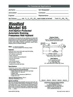
1 INSTALLATION INSTRUCTIONSMAINTENANCE INSTRUCTIONS1. Dig hole for hydrant approximately 2 feet in diameter and deeper than the bury Flush gravel, debris, etc. out of supply line before connecting Install hydrant with drain hole below frost wrenches on supply line fitting and brass valve body only. This avoids over tightening the hydrant assembly which could affect If supply line to the hydrant will not support hydrant , use re-bar, length of pipe or other suitable support driven in bottom of pit to help excavation, turn on water and check hydrant connection for Provisions must be made to allow the water to drain from the hydrant drain hole each time the hydrant is closed.
2 (a) If the hydrant is installed inside a structure or concrete driveway, connect 1/8 copper drain tubing to the drain hole and dig a remote drain field outside the structure for the drain pipe to empty into. Without this remote piping drain field, the water from the hydrant drainage surface around or near the hydrant and will damage the floor surface or cause muddy areas around hydrant .(b) Saturated ground in the hydrant drain field can prevent the hydrant from draining and may result in freezing. If the area where the hydrant is located is low lying or has a tendency to have standing water, a largerdrain field or pit may be required to provide the hydrant a place to drain.
3 (c) Fill bottom of pit with gravel to a level about 3 above brass drain valve body, to insure adequate drainage. Linkage AdjustmentThe adjustment can be made with the water supply on by tightening the packing nut enough to hold the hydrant increase the tension: With the hydrant in a closed position, loosen the set screw in the side of the pivot. Lift the handle, which should lift the linkage without moving the stem, to the desired location and reset the set decrease the tension: Lift the handle part way open and loosen the set screw in the side of the pivot.
4 Lower the handle, which should lower the linkage without moving the stem, to the desired location and reset the set handle, at the end of the closing stroke, should "snap" adjust the linkage, remove the lower link bolt that connects the lower link to the clevis assembly. Loosen the set screw in the lower link. Turn the lower link out (counterclockwise) to increase tension and in to decrease tension. The handle, at the end of the closing stroke, should snap closed. Tighten set screw. Install lower link & X34 Y34 & Y1 WOODFORDRFROSTLINEGROUND LEVEL04/10 Rev 2 tech -NOTE2121 Wa ynoka Road, Colorad o Spring s, Colo rado 809 15(7 19) 5 74 -1101(71 9) 574- 7621 Phone:F ax:For more information MANUFACTURING COMPANYA Division Of WCM Industries, Inc.
5 To view our complete product line visit: or email: of 2