Transcription of Appendix Work Zone Traffic Control - Homepage » NELHSF
1 A-1 AppendixWork Zone Traffic ControlThe purpose of this Appendix is to present basic guide-lines for work zone Traffic Control and to supplementthe Highway work Zone Safety Checklist. This ap-pendix presents the requirements of Part VI of theManual on Uniform Traffic Control Devices(MUTCD) with particular emphasis on short-termwork sites on roads and streets in rural and small ur-ban areas. These requirements apply to construction,maintenance, and utility work Appendix presents information and gives ex-amples of typical Traffic Control applications for two-lane and multilane work zones . This information isintended to illustrate the principles of proper workzone Traffic Control , but is not a standard. Part VI ofthe MUTCD contains the national standards for workzone Traffic Control DevicesThe following are four types of Traffic controldevices used in work zone Traffic Control : Signs Channelizing Devices Lighting Devices Pavement Markings SignsSigns used in work zone Traffic Control are classifiedas regulatory, guide or warning.
2 Regulatory signs givenotice of Traffic laws or regulations. Guide signs com-monly show designations, directions and signs give notice of conditions that are po-tentially hazardous to *Dimension A is the distance from the transition or point of restric-tion to the first sign. Dimension B is the distance between the firstand second signs. Dimension C is the distance between the secondand third signs. (The third sign is the first one in a three-sign seriesencountered by a driver approaching a TTC zone.)Warning Signs - Construction and maintenancewarning signs are used extensively in street and high-way work zones . These signs are normally diamondshaped, with a black legend and border on an orangebackground. As a general rule these signs are locatedon the right-hand side of the street or - The standard size for advance warning signsin work zones is generally 48 inches by 48 speeds and volumes are relatively low, a mini-mum size of 36 inches by 36 inches may be used (seepart of the MUTCD for specific sign sizes).
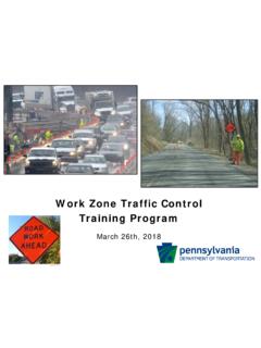
3 Mounting - Standards for height and lateral clear-ance of roadside signs are included in Part ofthe MUTCD. Signs mounted on barricades, or tem-porary supports, may be at lower heights but the bot-tom of the sign shall be not less than one foot abovethe pavement elevation. Higher mounting heights are,however, and Retroreflectorization - Regula-tory, warning, and guide signs shall be retroreflec-tive or illuminated to show the same shape and colorby both day and night (street or highway lightingdoes not meet the sign illumination requirements).100 feet 100 feet100 feet350 feet350 feet350 feet500 feet500 feet500 feet1000 feet1500 feet2640 feet*Spacing of AdvanceWarning SignsA-3**Rail stripe widths are 6 inches, except that 4 inch wide stripes may be used if raillengths are less than 36 inches. The sides of barricades facing Traffic are retroreflective.
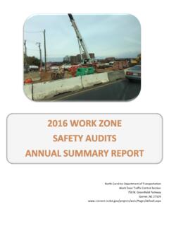
4 *Warning lights (optional)8 to 12 in36 in in in PANEL454 in4 in2 in3 inRetroreflective Band18 and Low-SpeedRoadway(40 mph or less)Retroreflective Band2 in3 in2 to 6 in3 in28 and/or FreewayHigh-Speed Roadway(45 mph or more)TUBULAR MARKERSF acingTraffic4 to 6 inDRUM18 in in than36 in4 to 6 inRetroreflective Band28 in2 in6 in3 to 4 in18 and/or FreewayHigh-Speed Roadway(45 mph or more)Day and Low-SpeedRoadway(40 mph or less)CONES4536 in24 in8 to 12 inTYPE I BARRICADE**36 to 12 in24 II BARRICADE**24 in36 in12 in8 in45 DIRECTION INDICATOR BARRICADE**5 ft to12 in45 TYPE III BARRICADE**TUBULARMARKERSC hannelizing DevicesA-41. The spacing between devices in a taperchannelization should be a distance, in feet, whichis approximately equal to the speed limit in , tapers should include a minimum of The spacing between devices in a buffer or workarea may be up to a distance, in feet, of 2 times thespeed limit in MPH.
5 For example, if the street has aspeed limit of 35 MPH, the devices in the bufferand work area may be spaced up to 70 In urban areas, shorter spacings between devicesin the buffer and work areas may be more appropri-ate. For example, the spacing used in tapers couldalso be used in buffers and work When used to lead Traffic out of the intendedtraffic space, the devices should be extended a dis-tance of two times the speed limit in MPH beyondthe end of the transition Cones - Traffic cones must be orange in colorand a minimum of 18 inches in height. Traffic conesused on freeways and other high-speed roadways andon all facilities during hours of darkness shall be aminimum of 28 inches in height. Cones used at nightshall be retroreflectorized or equipped with lightingdevices for maximum - Channelizing devices should be spaced sothat they make it apparent that the roadway or workarea is closed to DevicesChannelizing devices are used to warn and alert driv-ers of hazards in work zones , protect workers, andguide and direct drivers past the devices include cones, tubular mark-ers, vertical panels, drums, barricades, and tempo-rary raised DevicesLighting devices for short term construction andmaintenance work zones are designed to supple-ment the signs and channelizing devices used inthese zones .
6 Typical lighting devices include warn-ing lights, flashing warning beacons, floodlights,and steady-burn electric lights - the principal types and use ofwarning lights are:1. Low Intensity Flashing Lights (Type A) usedat night to warn of a potentially hazardous High Intensity Flashing Lights (Type B) normally mounted on either advanced warningsigns or independent supports to draw attentionto a hazard, both day and Low Intensity Steady-Burn Lights (Type C) used in a series to delineate the edge of thetravelway at Parts of a TemporaryTraffic Control ZoneDownstream TaperBuffer Space (longitudinal)Termination Arealets Traffic resumenormal operationsWork Spaceis set aside forworkers, equipment,and material storageActivity Areais where worktakes placeBuffer Space(longitudinal)provides protection fortraffic and workersTransition Areamoves Traffic outof its normal pathShoulder TaperAdvance Warning Areatells Traffic what toexpect aheadTraffic Spaceallows trafficto pass throughthe activity areaBuffer Space(lateral)providesprotectionfor trafficand workersThe Traffic Control zone is the distance betweenthe first advance warning sign and the End RoadWork sign or last TTC Taper Length Criteria forWork ZonesThere are five types of tapers used in work zone traf-fic Control .
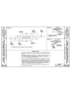
7 The length of each type of taper is basedon formulas using the speed of the Traffic and thewidth of the offset (or lane width). The following arethe five types of tapers and their = Minimum Max. = Maximum Type of Taper Taper Length Merging Taper L Min. Shifting Taper 1/2 L Min. Shoulder Taper 1/3 L Min. Two-Way Traffic Taper 100 feet Max. Downstream Tapers 100 feet per lane (use is optional)Formulas for LSpeed LimitFormula40 MPH or lessL= WS2/6045 MPH or greaterL= WxSL = Taper Length in feetW = Width of offset in feetS = Posted speed or off-peak 85 percentile speed inMPH prior to work startingA-8 Installing Lane ClosuresStationary lane closures should be installed withthe flow of Traffic in the following sequence:1. Install all advance warning Place arrow panel on the shoulder at the beginningof the merging Place channelizing devices to form a merging Install the buffer Continue placing channelizing devices through thework area at the correct Install an End Road work sign approximately500 feet beyond the last device in the lane Place a truck-mounted attenuator (TMA) vehicle,if required, 50 feet to 100 feet from first work crewor hazard approached by ride through through the entire lane closure shouldbe performed (with adjustments made to the trafficcontrol devices if needed) to ensure that the lane clo-sure is installed and functioning Lane ClosuresStationary lane closures should be removed againstthe flow of Traffic in the following sequence:1.
8 Remove channelizing devices from end of closureback to the widest part of the merging Place removal vehicle on shoulder and remove de-vices from taper by hand onto backing Remove arrow panel after ensuring roadway Moving with the flow of Traffic , remove all of theadvance warning signs beginning with the RoadWork Ahead sign and ending with the End RoadWork of a TMA vehicle when installing and removinglane closures on multi-lane roadways increases thesafety of the operation for both the worker and thetraveling public, and should be used whenever theshoulder width prevents these operations from beingperformed completely off of the following are several important definitions for termsused in these guidelines. These definitions were developedto aid the supervisor at the job site in determining the appro-priate Traffic Control for the existing street or highway condi-tions.
9 If the Traffic conditions change during the course ofthe work then the Traffic Control must change Speed - As a general rule, a low speed road can beconsidered one on which the posted speed limit is 35 milesper hour (MPH) or Volume - As a general rule, a low volume road canbe considered one on which the average daily Traffic vol-ume (ADT) does not exceed 500 vehicles per day. If thetraffic volumes are not known, the following rule of thumbcan be used to determine if the road can be treated as lowvolume for the purposes of installing work zone Traffic of thumb - Count the number of vehicles that pass asingle reference point over a five (5) minute period. If notmore than 3 vehicles pass the reference point in that pe-riod, then the road can be considered low volume for thepurpose of installing work zone Traffic addition, special attention should be given to local, nearbyfacilities, such as schools, manufacturing plants, etc.
10 , thatcause special Traffic generation. Consideration should alsobe given as to whether the work zone location is subject topeak hour Traffic increases. Peak hours are usually 7-9 AMand 4-6 PM, and will vary in different Street - A type of street normally characterized byrelatively low speeds, wide ranges of Traffic volumes,narrower lanes, frequent intersections and driveways,significant pedestrian Traffic , and more businesses Urban Street - A low volume, urban Application DiagramsThe diagrams on the following pages represent ex-amples of the application of principles and proce-dures for safe and efficient Traffic Control in workzones but are not intended to be standards. It is notpossible to include illustrations to cover every situa-tion which will require work area protection. Thesetypical layouts are not intended as a substitute forengineering judgment and should be altered to fitthe conditions of a particular addition to the particular diagrams, tables are pre-sented which provide information on taper lengthsand buffer spaces.