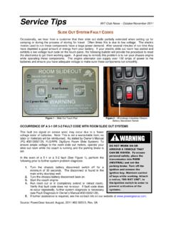
Transcription of Zapi FC2086 Codes - FSIP
1 zapi FC2086 Status CodesController AdjustmentsThe zapi transistor motor controller can store and display Error Codes (Alarms). It is also possibleto modify the controller Setup for individual preferences. Communication with the controller is possible by four methods:1. LED - An LED may be installed in trucks that do not use a dash display. The LED flashes error Codes to the technicianfor diagnosis. The LED would be installed on the bottom of the zapi controller. The LED is installed in the connector port2. Dash Display - Some trucks are equipped with an optional dash display or MDI. Error Codes are shown on the LCDwhen the wrench symbol and red light are lit. The format is AL XX where XX is the error zapi Handset - A diagnostic handset is available thru your Hyster or Yale dealer. The handset makes it possible to diagnose faults and modify controller settings. 4. Personal Computer - The controller can also be connected to a PC equipped with special software and cables.
2 The PCcan read, store, and change settings on the use of these four methods and list of diagnostic Codes are explained in this : General error code information is provided by the Dash Display and Red LED at the base of the most instances, it will be necessary to use a handset or a PC to further define the possible causesand test DisplayController LEDH andset or PCCONDITIONNo LEDs or LCDs illuminatedLED OFF Handset does not operateDash display, controller LED, and truck inoperativeTRUCK RESPONSET ravel and hydraulic functions CAUSES AND TEST PROCEDURES B+ and/or B missing at battery is connected and of proper key switch is brake override circuit is connected in continuity between batteries negative (atbattery) and B power wire connection (at controller).If no continuity, check:Power wiring between battery and for +24V at D-4, A-3, and no continuity, check:Fuse 2 for switch continuity in ON battery + to main contactor to fuse 2 tokey switch, to controller A-6 connection.
3 Defective battery chargerDisconnect wires 2D and 12 from leads to battery test lead to connect 2D and truck operates, check charger fuses,repair or replace battery charger. Defective motor for battery voltage between A-6 and B-power wire connection at correct battery voltage, replace DisplayController LEDH andset or PCCONDITIONNo LEDs or LCDs illuminatedLED OFF No error Codes presentDash display and/or controller LED RESPONSET ravel and hydraulic functions CAUSES AND TEST PROCEDURES Open connection between dash display and harness connections at MDI and connectorB on continuity of wires between MDI and controller. Defective dash handset to controller and confirm communicationto handset operates correctly, replace REFERENCE ONLY 5/4/10 Rev A Defective LED and connect handset. If handsetworks, replace DisplayController LEDH andset or PCCONDITIONNo LEDs or LCDs illuminatedLED OFF NO COMMUNICATIONDash display and/or controller LED RESPONSET ravel and hydraulic functions CAUSES AND TEST PROCEDURES Defective handset to controller and confirm communicationto handset will not communicate with controller,replace DisplayController LEDH andset or PCCONDITIONNo AlarmLED OFF - No FlashesINCORRECT STARTI mproper startup sequence by RESPONSET raction and hydraulic functions CAUSES AND TEST PROCEDURES Throttle or hydraulic function selected at key handle in run position at key steer handle to full upright position.
4 Returnthrottle to neutral. Release all hydraulicfunction fault remains, attach handset and go to test menu. Check brake switch, it should be off. If steer handleis in vertical position and reading is not OFF, checkbrake switch for damage, interference, or shorts. Check accelerator - Should be 0 volts at neutral. Ifnot, repeat control card calibration. If this does notcorrect the problem, replace control card. Check hydraulic inputs Should be 0 volts. If not,recalibrate tiller card. Follow auto-learn procedurelisted in steering. If this does not clear fault, checkbuttons for damage or interference. Replace damagedor faulty DisplayController LEDH andset or PCCONDITIONAL66 Continuous FlashingBATTERY LOWB attery discharged and requires RESPONSEH ydraulic lift function CAUSES AND TEST PROCEDURES Battery voltage is or replace battery. Controller voltage calibration is handset. Go to test menu and selectBattery Voltage.
5 Compare tester voltage to voltagemeasured by an accurate digital voltmeterbetween B+ and B terminals. Pull down tillerhandle to engage contactor for this these two voltages are more than difference, replace DisplayController LEDH andset or PCCONDITIONAL99 Continuous FlashBATTERY KOImproper battery connection or defective RESPONSET raction and hydraulic functions CAUSES AND TEST PROCEDURES Incorrect battery correct battery voltage for truck. Damaged or extremely discharged battery and check voltage at battery for correct water level andFOR REFERENCE ONLY 5/4/10 Rev Adamage. Repair or replace battery. Defective or damaged connection to cable crimps and cables from battery cable crimps and cables frombattery contactorto controller and DisplayController LEDH andset or PCCONDITIONAL011 FlashVACC NOT OKConnection/communication error between tiller card and traction RESPONSET raction and hoist functions CAUSES AND TEST PROCEDURES Control card throttle calibration is out of handset.
6 Go to tester function of accelerator output is >1V (20%) and the enableswitch is open, recalibrate control card. Control card throttle damaged or card cannot be recalibrated, replace DisplayController LEDH andset or PCCONDITIONAL011 FlashPUMP VACC NOT OKConnection/communication error between controlcard and traction RESPONSET raction and hoist functions CAUSES AND TEST PROCEDURES A lift/lower switch is damaged or handset. Go to tester function. Checklifting control and EVP voltage. Check on/offswitches for smooth, linear damaged switches. Control card lift/lower switch calibration is out of handset. Go to tester function. Check liftingcontrol and EVP voltage. Output of hydrauliccontrols should be less than 1V (20%) at control card. Control card is damaged or DisplayController LEDH andset or PCCONDITIONAL011 FlashFORW + BACKC onnection/communication error between controlcard and traction RESPONSET raction and hoist functions CAUSES AND TEST PROCEDURES Control card throttle device is damaged or handset.
7 Go to tester function. If forwardswitch and backward switch are both on at thesame time, card is control DisplayController LEDH andset or PCCONDITIONAL011 FlashSERIAL ERROR #1 Connection/communication error between controlcard and traction RESPONSET raction and hoist functions CAUSES AND TEST PROCEDURES Loose or damaged electrical connection betweencontrol card and connection at wire harness connection at base of steer connection at control card. Damaged or defective control voltage at pin 5, connector C, on thecontroller. With control card disconnected, thisFOR REFERENCE ONLY 5/4/10 Rev Ashould be about 12V; with the card connected, itshould be about 5V. 0V or 12V with the card connectedmeans that the card is control DisplayController LEDH andset or PCCONDITIONAL011 FlashINPUT ERROR #1 Connection/communication error between controlcard and traction RESPONSET raction and hoist functions CAUSES AND TEST PROCEDURES Traction reversing switch is not handset.
8 Go to tester function. Check foroperation of traction reversing that traction reversing switch cover ismaking contact with switch on control wires in control handle arm are secure. Damaged or defective control control DisplayController LEDH andset or PCCONDITIONAL011 FlashINPUT ERROR #2 Connection/communication error between controlcard and traction RESPONSET raction and hoist functions CAUSES AND TEST PROCEDURES Traction reversing switch is not handset. Go to tester function. Check foroperation of traction reversing that traction reversing switch cover ismaking contact with switch on control card. Damaged or defective steer handle control cable for loose connectionsor broken wires. Damaged or defective control handle control DisplayController LEDH andset or PCCONDITIONAL02 2 FlashesCONTACTOR CLOSEDMain contactor circuit is RESPONSET raction and hydraulic functions CAUSES AND TEST PROCEDURES Main contactor tips are welded power leads at contactor.
9 Use meterto confirm open circuit across power short circuit is measured, replace contactor. Problem in motor field electrical connections between motor fieldand motor field for shorts to chassis. Controller is DisplayController LEDH andset or PCCONDITIONAL44 FlashesEVP NOT OKLowering valve will not operate RESPONSET raction and hydraulic functions CAUSES AND TEST PROCEDURES Damaged or loose electrical connection tolowering electrical connections betweenvalve coil and controller. Lowering coil lowering valve coil for correct resistance should be approximately 33 REFERENCE ONLY 5/4/10 Rev AReplace coil if damaged. Lowering valve cartridge is lowering valve DisplayController LEDH andset or PCCONDITIONAL55 FlashesEB DRIVER KOElectric brake does not release or remainsreleased at all RESPONSET raction and hydraulic functions CAUSES AND TEST PROCEDURES Damaged or loose electrical connection to electrical connection between electricbrake and controller.
10 Check brake coil for correct coil brake. Measure brake coil resistancein both directions. Coil resistance should be and ohms. Damaged the brake switch. Use voltmeter tomeasure voltage on wire 2C and 17 with brakeconnected in circuit. If both measurements are24V and the alarm is displayed, then controlleris DisplayController LEDH andset or PCCONDITIONAL66 FlashesV FIELD NOT OKVoltage measured at field connections is not RESPONSET raction and hydraulic functions CAUSES AND TEST PROCEDURES Cable connection to motor field is loose or connection of field wires to motor and controller. Check condition of crimps on wires connecting to F1and DisplayController LEDH andset or PCCONDITIONAL66 FlashesI = 0 EVERM otor current levels do not exceed a presetminimum value while RESPONSET raction and hydraulic function CAUSES AND TEST PROCEDURES Damaged or loose electrical connections to electrical connections between tractionmotor and controller.