Transcription of Trailer | Remolque | Remorque Cable | Cable | …
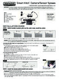
1 2009920400 SELF-TAP SCREWSBREAK-AWAY SWITCHBREAK-AWAY SYSTEM INSTRUCTIONSfor 1 - 2 axle trailersThe following instructions must be precisely followed to ensure proper read the following instructions thoroughly before installing this product. YOUR Trailer MUST HAVE OPERATIONAL ELECTRICAL BRAKES TO USE THIS PRODUCTMake sure you have all parts before you start your Engager Break-Away System is designed to bring trailers safely to a stop by activating electric brakes, should a Trailer be disconnected while driving. This type of safety system is required in most states on trailers rated over 3,000 GVW. Note: Contact your department of transportation for complete towing law information. Your Trailer must have operational electric brakes before installation .
2 Once you determine your Trailer brakes work. find a secure location on your Trailer to mount the Break-Away Box. Mounting Instructions1. Locate secure surface on Trailer to mount Break-Away With flat washers on each screw, route through provided holes in each corner of the Break-Away kit plastic casing. Use screwdriver or drill and secure to Trailer . 3. Next mount Brake-Away Switch close enough on Trailer that the Cable can be attached to Follow Wiring installation .Additional Information for Model Numbers 20099, and 204001. The Trailer plug should be detached from the towing vehicle when using the push to test feature to test the Break-Away battery voltage level. Otherwise you will be testing the towing vehicle s If the Trailer is plugged into the tow vehicle, the yellow Charging light will always be on3.
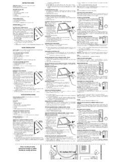
3 The LED assembly will only work with 12-volt batteries. The lower the battery voltage goes, the dimmer the LEDs will illuminateWiring Installation1. Splice the blue wire of the Break-Away Switch to the electric brake wire coming from the Trailer side connector2. Connect the black (labeled battery) wire of the Break-Away Switch to the blue wire (labeled brake) from the Break-Away Box3. Splice white wire from Break-Away Box to existing ground wire on Trailer or ground directly to Trailer frame4. Splice black wire on Break-Away Box to Trailer 12-Volt auxiliary power lead. This will charge the Break-Away Battery when vehicle is in use. NOTE: Some break-away systems do not have a black wire. These systems will require the battery be fully charged, by a trickle charger, before DIAGRAM ON BACK Cable INSTALLATIONFIG 1 FIG 2 FIG 3 CABLECABLECABLEBREAK-AWAYSWITCHBREAK-AWA YSWITCHBREAK-AWAYSWITCHBUMPERCLEVISSAFET Y CHAIN POCKETPINB reak-Away Switch Setup1.
4 Test unit by pulling firmly on Cable of Break-Away Switch. Battery will activate brakes. Note: Do not pull pin from the Break-Away switch if the Trailer is electrically connected to the tow vehicle. This could result in damage to the tow Once tested, Break-Away Switch Cable should be secured to vehicle bumper or frame. The Cable can be attached many dif-ferent ways. Two of the most common are: I. Pull the pin out of the Break-Away Switch (FIG 1) and route through safety chain pocket (FIG 2), then through Cable loop and reconnect pin. II. Attach Cable loop to a bumper clevis (FIG 3). Do not loop Cable over hitch ball. Cable could bounce off while vehicle is moving. Note: Pin must be facing the rear of the vehicle, directly behind the location of the Cable on your vehicle.
5 Anything else may cause Break-Away Switch MUST BE FULLY CHARGED BEFORE USE For models with push to test and battery status indicators: If the red light illuminates when the test button is pushed, the battery charge is low. If the charge is low, connect the Trailer plug to the tow vehicle so the Break-Away Kit can charge (This can only be done after kit is installed on Trailer ). The amber light will illuminate indi-cating the battery is charging. The battery should re-charge in about twenty minutes. For models without push to test and battery status indicators: Check battery charge with a battery tester. If charge is low, Connect the Trailer plug to the tow vehicle so the Break-Away kit can charge (This can oly be done after kit is installed on Trailer ).
6 Electric Brake (Blue)Freno El ctrico (Azul)Frein lectrique (Bleu)Ground (White)Conexi n a Tierra (Blanco)Masse (Blanc)Black | Negro | NoirWhite | Blanco | BlancBlue | Azul | BleuBlue | Azul | BleuBlack | Negro | NoirBreak-Away SwitchInterruptor Break-AwayInterrupteur Break-AwayBreak-Away BoxCaja Break-AwayBo tier Break-AwayTrailer | Remolque | Remorque Cable | Cable | C bleTrailer WiringCableado del RemolqueC blage de la RemorqueSplices | Empalmes | pissuresTrailer ConnectorConector del RemolqueConnecteur de la RemorqueDIAGRAMME AVEC CHARGEUR DIAGRAMA CON EL CARGADOR WIRING DIAGRAM WITH CHARGER 12-Volt Battery(Red or Black)Conductor de bater a de 12 voltios(Negro o Rojo)Conducteur de batterie de 12 volts(Roir ou Rouge) 2015 Hopkins Manufacturing Corporation Rev G | 311-0288-029 installation du c bleFIG 1 FIG 2 FIG 3C BLECOMMUTATEUR DE D SACCOUPLEMENTCOMMUTATEUR DE D SACCOUPLEMENTCOMMUTATEUR DE D SACCOUPLEMENTCHAPE DE REMOR-QUAGE DU PARE-CHOCSPASSANT POUR CHA NE DE S CURIT BROCHEC onfiguration du commutateur de d saccouplement1.
7 V rifier que le n cessaire est bien install en tirant fermement sur le c ble du commutateur. La batterie activera les freins. Remarque : Si la Remorque est branch e au v hicule remorqueur, ne pas retirer la broche du commutateur. Cela pourrait endommager le v Apr s v rification, attacher le c ble du commutateur au pare-chocs ou au cadre du v hicule. On peut proc der de diff rentes fa ons. Voici deux m thodes parmi les plus courantes : I. Retirer la broche du commutateur (fig. 1) et ins rer le c ble dans le passant pour la cha ne de s curit (fig. 2) puis dans la boucle du c ble. Remettre la broche. II. Attacher la boucle du c ble la chape de remorquage sur le pare-chocs (fig. 3). Ne pas passer la boucle sur la boule d attelage : le c ble pourrait se d -placer pendant que le v hicule est en marche.
8 Remarque : La broche doit tre orient e vers l arri re du v hicule, directement derri re l endroit o le c ble est fix . Toute autre disposition pourrait entra ner une d faillance du commutateur de d , 20100, 2010120400, 20401 VIS AUTOTARAUDEUSESCOMMUTATEUR DE D SACCOUPLEMENTINSTRUCTIONS D installation DU N CESSAIRE DE D SACCOUPLEMENT pour les remorques un ou deux essieuxIl faut suivre la lettre les instructions ci-dessous pour garantir le bon fonctionnement du syst me. Lire attentivement les instructions suivantes avant d installer le produit. S assurer d avoir en main toutes les pi ces avant de commencer l installation . Le syst me de d saccouplement est con u pour immobiliser une Remorque de fa on s curitaire, gr ce l application des freins lectriques, en cas de d tachement de la Remorque .
9 Ce type de syst me de s curit est exig par la plupart des provinces et territoires sur les remorques dont le poids nominal brut est sup rieur 1 360 kg (3 000 lb). Remarque : Renseignez-vous sur la l gislation relative au remorquage aupr s du minist re des Transports de votre province. L installation de ce syst me exige que la Remorque soit quip e de freins lectriques fonctionnels. Apr s avoir v rifi le fonctionnement des freins, choisir un endroit s curitaire o monter le bo tier de d saccouplement. Ce syst me peut tre assembl de deux fa ons. Instructions de montage1. Busque una superficie segura en el Remolque para montar el kit Break-Away. 2. Introduzca los tornillos con arandelas planas en los orificios presentes en cada esquina de la carcasa pl stica del kit Break-Away.
10 Use un destornillador o un taladro para fijarlos al suppl mentaires pour les mod les 20099, 20100 et 204001. La fiche de la Remorque doit tre d branch e du v hicule remorqueur pour utiliser le bouton d essai et v rifier la tension de la batterie de l ensemble de d saccouplement. Autrement, vous testeriez la charge de la batterie du v Si la Remorque est branch e au v hicule remorqueur, le voyant de charge jaune demeure allum L ensemble de DEL fonctionne seulement avec des piles de 12 V. Plus la tension de la batterie est faible, moins les DEL sont APPAREIL DOIT TRE ENTI REMENT CHARG AVANT L UTILISATION Pour les mod les avec poussoir pour tester et indicateurs de l tat de la batterie: Si le voyant rouge s allume lorsqu on appuie sur le bouton d essai, la charge de la batterie est faible.