Transcription of FCM8202 3-Phase Sinusoidal Brushless DC Motor Controller
1 March 2013 2010 Fairchild Semiconductor Corporation FCM8202 Rev. FCM8202 3-Phase Sinusoidal Brushless DC Motor Controller FCM8202 3-Phase Sinusoidal Brushless DC Motor Controller Features Supports Space Vector Modulation (SVM) Supports Sine-Wave & Square-Wave Solutions Built-in Clock Generator Built-in Error Amplifier for Torque Loop Control Direct Duty Control Square-Wave 120 , Sine-Wave 180 Turn-on PLL Angle Detection (Hall Sensors) Current Leading Phase Correction Two Selectable Dead Times Synchronous Rectifying Over-Voltage and Under-Voltage Protections Motor and Power Transistors for Over-Voltage Protections (OVP) three Levels of Over-Current Protections (OCP) Adjustable OC Timer Over-Temperature Protection (OTP) Applications BLDC Motor or PMSM Control Low Noise Motor Applications Fan, Pump, Tools, etc.
2 Description FCM8202 is a three -phase Sinusoidal Brushless DC (BLDC) Motor or Permanent Magnet Synchronous Motor (PMSM) Controller . It comes with the advanced Hall sensor design. Using the Hall sensor signals, the control system is able to execute the PWM commutation by switching the three -phase inverter. There are two PWM modes: Sine-Wave Mode and Square-Wave Mode. The Square-Wave Mode includes PWM-PWM and PWM-ON approaches to improve the efficiency of the Motor drive.
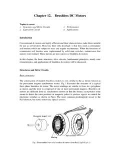
3 Complete protection functions including over-voltage, over-current, over-temperature, and short-circuit protections prevent the control circuits and the Motor from being damaged, particularly under stressed applications and demanding environments. Ordering Information Part Number Operating Temperature Range Package Packing Method FCM8202QY -40 C to 125 C 32-Lead, LQFP, JEDEC MS-026, Variation BBA, 7 mm Square Tray 2010 Fairchild Semiconductor Corporation FCM8202 Rev. 2 FCM8202 3-Phase Sinusoidal Brushless DC Motor Controller Typical Application Circuit Figure 1.
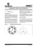
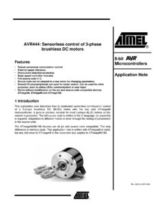
4 Typical Application Circuit Block Diagram Figure 2. System Block Diagram 2010 Fairchild Semiconductor Corporation FCM8202 Rev. 3 FCM8202 3-Phase Sinusoidal Brushless DC Motor Controller Marking Information Figure 3. Top Mark Pin Configuration Figure 4. Pin Configuration F- Fairchild Logo Z- Plant Code X- 1-Digit Year Code Y- 1-Digit Week Code TT: 2-Digit Die Run Code T: Package Type (Q=LQFP) P: Y=Green Package M: Die Run Code 2010 Fairchild Semiconductor Corporation FCM8202 Rev. 4 FCM8202 3-Phase Sinusoidal Brushless DC Motor Controller Pin Definitions Pin # Name Description 1 HOVP Motor Drive Over-Voltage Protection Output.
5 Can be connected to an external power transistor for discharging the Back-EMF. 2 HA Hall A Sensor Input. Phase-U magnetic field detection. 3 HB Hall B Sensor Input. Phase-V magnetic field detection. 4 HC Hall C Sensor Input. Phase-W magnetic field detection. 5 CW/CCW Direction Control Input. This pin has a 200 k internal pull-up. HIGH: CW, LOW: CCW. 6 FREE/nST Free and Start Control Input. This pin has a 200 k internal pull-up.
6 HIGH: Free, LOW: Start. 7 APRS Angle Predict Range Selection Input. This pin has a 200 k internal pull-up. LOW: ~ 80 Hz, HIGH: ~ 320 Hz Hall Frequency. 8 DTS Dead-Time Selection Input. This pin has a 200 k internal pull-up. LOW: 3 s, HIGH: 4 s. 9 FO Revolution Pulse Output. Pulses per revolution = Motor poles 2 3. 10 DGND Digital Ground 11 VOUT Voltage Regulator Output. A F (minimum) capacitor should be connected between this pin and ground.
7 12 IP Positive Input of Torque Error Amplifier 13 OPO Output of Torque Error Amplifier 14 IN Negative Input of Torque Error Amplifier 15 I_FB Current Feedback Output 16 DUTY PWM Duty Control Input. Designed to directly control the PWM duty cycle. 17 R_CLK External Resistor of Clock Generator. Designed for determining the frequency of internal clock generator. 18 AGND Analog Ground 19 I_IN Current Feedback Input 20 AS Angle Shift Input.
8 Designed for correcting the lead angle of PWM output signals. The range is from 0 to 60 related to the induced magnetic voltage. 21 VSENSE Motor Drive Voltage-Sensing Resistor. Designed for determining the voltage level of over-voltage protections. 22 RT Thermistor Voltage Input. Connect to a Negative Temperature Coefficient (NTC) thermistor for the over-temperature protection. 23 OC_TMR Overload Time-Out Programmable Input. Connect to a capacitor for determining the time delay of overload protection.
9 24 nFAULT Fault Flag. Open-drain output, LOW: system failure. 25 VPP Supply Voltage Input 26 Z PWM Output of W-Phase, Low-Side 27 W PWM Output of W-Phase, High-Side 28 Y PWM Output of V-Phase, Low-Side 29 V PWM Output of V-Phase, High-Side 30 X PWM Output of U-Phase, Low-Side 31 U PWM Output of U-Phase, High-Side 32 PGND High-Voltage Ground 2010 Fairchild Semiconductor Corporation FCM8202 Rev. 5 FCM8202 3-Phase Sinusoidal Brushless DC Motor Controller Absolute Maximum Ratings Stresses exceeding the absolute maximum ratings may damage the device.
10 The device may not function or be operable above the recommended operating conditions and stressing the parts to these levels is not recommended. In addition, extended exposure to stresses above the recommended operating conditions may affect device reliability. The absolute maximum ratings are stress ratings only. Symbol Parameter Min. Max. Unit VPP Supply Voltage 0 30 V JA Thermal Resistance, Junction-to-ambient 82 C/W JC Thermal Resistance, Junction-to-case 29 C/W TJ Junction Temperature +150 C ESD Electrostatic Discharge Protection Level Human Body Model, JESD22-A114 kV Charged Device Model.