Transcription of Industrial Data Communications – RS-232/RS-485
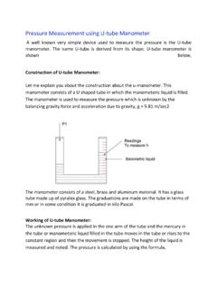
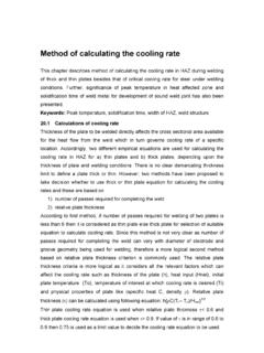
1 Industrial data Communications RS-232/RS-485 Tutorial 2 This tutorial on Industrial data Communications is broken down into the following sections:wBalanced and Unbalanced SystemswRS-232wRS-485 Balanced and Unbalanced SystemsThe choice between unbalanced and balanced transmission lines is an importantconsideration when selecting a data Communications system. The RS-232 standard is aunbalanced standard; whereas the RS-485 standard is balanced. Strictly speaking thesestandards should be referred to as EIA-232E and EIA-485 respectively; but for the purposesof this tutorial, RS (or Recommended Standard) will be data Communications systems using the RS232 interface standards, the voltage signalis said to be unbalanced because only one wire carries the signal voltage. There is also asignal common wire, sometimes called the signal ground. The transmitted signal is thevoltage between the signal conductor and the common reference 1 data communication with Unbalanced InterfacesCommunication interfaces operating in accordance with the EIA485 interface standardsrequire two conductors to transmit each signal.
2 The voltage at the receiving end is measuredas the voltage difference between these two wires. This is known as a balanced or differentialsystem. This eliminates many of the interference problems associated with the commonreference voltage between the signal conductor and the common reference conductor is knownas a common mode voltage (CMV). Ideally the CMV on the two wires will cancel outcompletely but the greater the CMV, the higher the voltage difference and the the morelikely that noise will affect the signal. If the CMV reaches a certain high threshold, theerrors will increase to an unacceptable 2 data Communications with Balanced InterfacesThe balanced transmission line permits a higher rate of data transfer over longer differential method of data transfer is preferable in Industrial applications where noisecan be a major problem. The disadvantage is that a balanced system requires two conductorsfor every successful transfer of voltage signals across two conductors in the presence of noiseis based on the assumption that the conductors have similar characteristics and will beaffected equally by noise and voltage drops, for example.
3 It does not mean that noise doesnot exist in the balanced differential system. The voltages on both conductors should riseand fall together, and the differential voltage should remain the RS-232 standardThe RS-232 Interface Standard was developed for a single purpose which is clearly statedin its title, the Interface between data Terminal Equipment (DTE) and data CircuitTerminating Equipment (DCE) employing serial binary data interchange . In particular, EIA-232 was developed for interfacing data terminals to interpretation of RS-232 has been responsible for many problems in interfacingequipment from different manufacturers, leading some users to dispute whether it is a standard . It should be emphasised that RS-232, and other related EIA standards, definethe electrical and mechanical details of the interface and do not define a protocol (theactual packet and message structure).
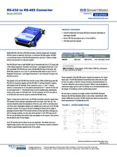
4 The RS-232 interface standard specifies the method of connection of two devices, theDTE and data Terminal Equipment, for example, may be a computer or a printer. A DTE devicecommunicates with a DCE device. A DTE device transmits data on pin 2 and receivesdata on pin data Communications Equipment, now also called data Circuit-terminating Equipmentin EIA/TIA-232E, for example a modem. A DCE device receives data from the DTE andretransmits via another data Communications link, such as the telephone system. A DCEdevice transmits data on pin 3 and receives data on pin 3 Connections Between the DTE and the DCEE quipment that uses the RS-232 standard has the following features:wpoint-to-point communicationwsuitable for serial, binary and digital data communicationwcommunication is generally asynchronous, meaning that there is fixed timingbetween data bits, but variable time between character frameswfull duplex communicationswUnbalanced transmission (and therefore susceptible to noise)voltage signals are:logic 1: -3 V to -25 Vlogic 0: +3 V to +25 Vreliable communication up to a distance of about 50ft, depending on the type of cable usedand the speed data rates of up to about 20kbps according to the standard (but 115 kBaudin practice).
5 The EIA-232 standard defines 25 electrical connections. The electricalconnections are divided into four groups:wdata lineswcontrol lineswtiming lineswspecial secondary functionsPin ConnectorDB-25 ConnectorDB-25 ConnectorDTEEIA-232 Pin AssignmentEIA-232 Pin AssignmentEIA-530 Pin Assignment1 Received Line SignalShieldShield2 Received DataTransmitted DataTransmitted data (A)3 Transmitted DataReceived DataReceived data (A)4 DTE ReadyRequest to SendRequest to Send (A)5 Signal/Common Ground Clear to SendClear to Send (A)6 DCE ReadyDCE ReadyDCE Ready (A)7 Request to SendSignal/Common GroundSignal/Common Ground8 Clear to SendReceived Line SignalReceived Line Signal (A)9 Ring Indicator+Voltage (testing)Receiver SignalDCE Element Timing (B)10-Voltage (testing)Received Line (B)11 UnassignedTransmitter SignalDTE Element Timing (B)12 Sec Received Line SignalTransmitter SignalDetector/ data SignalDCE Element Timing13 Sec Clear to SendClear to Send (B)
6 14 Sec Transmitted DataTransmitted data (B)15 Transmitter SignalTransmitter SignalDCE Element TimingDCE Element Timing (A)16 Sec Received DataReceived data (B)17 Receiver SignalReceiver SignalDCE Element TimingDCE Element Timing (A)18 Local LoopbackLocal Loopback19 Sec Request to SendRequest to Send (B)20 DTE ReadyDTE Ready (A)21 Remote Loopback/SignalRemote LoopbackQuality Detector22 Ring IndicatorDCE Ready (B)23 data Signal RateDTE Ready (B)24 Transmit SignalTransmitter SignalDTE Element TimingDTE Element Timing (A)25 Test ModeTestTable 1 Table of Common DB-9 and DB-25 Pin Assignments for EIA-232 and EIA/TIA-530 (often used for EIA-422and EIA-485)The EIA-485 Interface StandardThe EIA-485 standard is the most versatile of the EIA interface standards and is a truebalanced or differential standard. EIA-485 permits a multidrop network connection on 2wires and allows reliable serial data communication for:wdistances of up to 1200mwdata rates of up to 10 Mbpswup to 32 line drivers on the same linewup to 32 line receivers on the same major enhancement of EIA-485 is that a line driver can operate in three states calledtri-state operation:w logic 1w logic 0w high-impedanceIn high impedance the line driver draws virtually no current and appears not to be presenton the line.
7 This is known as the disabled state and can be initiated by a signal on acontrol pin on the line driver integrated circuit. Tri-state operation allows a multidrop networkconnection and up to 32 transmitters can be connected on the same line, although onlyone can be active at any one time. Each terminal in a multidrop system must be allocateda unique address to avoid conflicting with other devices on the system. EIA-485 includescurrent limiting in cases where contention EIA-485 interface standard is very useful for systems where several instruments orcontrollers may be connected on the same line. Special care must be taken with the softwareto co-ordinate which devices on the network can become active. In most cases a masterterminal, such as a PC or computer, controls which transmitter/receiver will be active atany one 2-wire data transmission line does not normally require special termination.
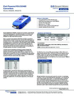
8 On longlines, the leading and trailing edges of data pulses will be much sharper if terminatingresistors approximately equal to the characteristic impedance (Zo) of the line are fitted atthe extreme ends. This is indicated in Figure 4. For twisted pairs the characteristicimpedance is typically between 100 to 120 4 Typical Two Wire Multidrop NetworkAn EIA-485 network can also be connected as a four wire configuration. In this type ofconnection it is necessary that one node be a master node and all others be slaves. Themaster node communicates to all slaves, but a slave node can communicate only to themaster. Since the slave nodes never listen to another slave s response to the master, aslace node cannot reply incorrectly to another slace node. This is an advantage in a mixedprotocol environment.