Transcription of Series 3725 Type 3725 Electropneumatic Positioner - SAMSON
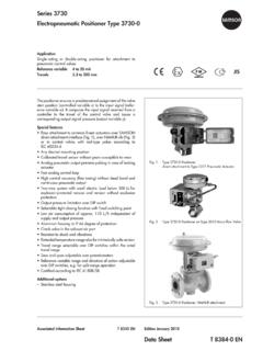
1 Series 3725 Electropneumatic PositionerType 3725 Mounting andOperating InstructionsEB 8394 EN (1300-1621)Firmware version February 2012 Fig. 1 Type 3725 Positioner2EB 8394 ENWARNING!indicates a hazardous situation which, if notavoided, could result in death or a property damage :Supplementary explanations,information and tipsDefinitions of the signal words used in these instructionsContentsPage1 Safety instructions.. 62 Article code.. 73 Design and principle of operation.. data.. 104 Attachment to the control valve Mounting parts and accessories.
2 Attachment .. 3277-5 Actuator .. 3277 Actuator .. according to IEC 60534-6 .. to Type 3372 Actuator (V2001) .. to rotary actuators .. parts and accessories .. 265 Connections.. connections.. pressure gauges .. pressure .. connections .. 296 Operation.. controls .. 327 Start-up Settings.. configuration.. the volume restriction Q .. the display.. the opening direction .. the direction of action.. the signal pressure.. other parameters .. calibration .. mode .. 41EB 8394 .. 428 Code list.. 439 Maintenance.
3 4710 Servicing explosion-protected devices.. 4711 Dimensions in mm.. levels according to VDI/VDE 3845 (September 2010) .. 49 Test certificates.. 504EB 8394 ENContentsEB 8394 EN5 Firmware revisionsFirmware (previous) (new)Internal revisions1 Safety instructionsFor your own safety, follow these instructions concerning the mounting, start up and opera-tion of the Positioner :4 The Positioner is to be mounted, started up or operated only by trained and experi-enced personnel familiar with the to these Mounting and Operating Instructions, trained personnel refers toindividuals who are able to judge the work they are assigned to and recognize possi-ble dangers due to their specialized training.
4 Their knowledge and experience as wellas their knowledge of the relevant versions of this Positioner may only be operated by personnelwho have undergone special training or instructions or who are authorized to workon explosion-protected devices in hazardous hazards that could be caused by the process medium, the operating pressure, thesignal pressure or by moving parts of the control valve are to be prevented by meansof the appropriate inadmissible motions or forces are produced in the actuator as a result of the supplypressure, the supply pressure must be restricted by means of a suitable supply pres-sure reducing shipping and appropriate storage are avoid damage to any equipment, the following also applies.
5 4Do not operate the Positioner with the back of the Positioner /vent opening facing vent opening must not be sealed when the Positioner is installed on not ground electric welding equipment near to the :The device with a CE marking fulfills the requirements of the Directives 94/9/EC(ATEX) and 89/336/EEC (EMC).The Declaration of Conformity is available on 8394 ENSafety instructionsVent opening2 Article codeEB8394 EN7 Article codePositionerType 3725-xxx00000009999 With LCD and autotune, 4 to 20 mA reference variableExplosion protection*Without000II 2 G Ex ia IIC T4 acc.
6 To ATEX1100* Other approvals in preparation3 Design and principle ofoperationThe Electropneumatic Positioner is mountedon pneumatic control valves. It is used to as-sign the valve stem position (controlled vari-able x) to the control signal (reference vari-able w). The electric control signal receivedfrom a control system is compared to thetravel or rotational angle of the control valveand a signal pressure (output variable y) isproduced for the pneumatic Positioner consists of an anisotropicmagnetoresistive (AMR) sensor (2), an ana-log i/p converter (7) with a downstreambooster and the electronics unit withmicrocontroller (4).
7 The travel or opening angle is measured bythe pick-up lever connected to a magnet anda non-contact AMR sensor (2) installed inthe housing and the motion of the pick-up lever causes thedirection of the magnetic field to change is sensed by the AMR microprocessor determine the momen-tary valve position from this position of the valve is transmitted to themicrocontroller (4) over the A/D converter(3). The PD control algorithm in the micro-processor (4) compares this actual positionto the 4 to 20 mA control signal (referencevariable) after it has been converted by theA/D converter (3).
8 In case of a system deviation, the operationof the i/p converter (6) is changed so thatthe actuator (1) is filled or vented by thedownstream air capacity booster (7).The pneumatic air capacity booster (7) andthe pressure regulator (8) are supplied withsupply output signal pressure supplied by thebooster can be limited to bar by volume restriction Q (10) is used to opti-mize the Positioner by adapting it to the ac-tuator functionThe pneumatic actuator is completely filledwith air or vented as soon as the referencevariable falls below 1 % or exceeds 99 %(see end positions set over parameter codesP10 and P11).
9 Air to open (ATO): P10 ON; P11 OFFAir to close (ATC): P10 OFF; P11 ON8EB8394 ENDesign and principle of operationEB8394 EN9 Design and principle of operation%Smm%mmQ3411678101w9xy25 Fig. 2 Functional diagram1 Control valve2 AMR sensor3 A/D converter4 Microcontroller5 D/A converter6 i/p converter7 Air capacity booster8 Pressure regulator9 Fixed restriction10 Volume restriction11 Technical data10EB8394 ENTechnical dataType 3725 PositionerTravel, adjustableDirect attachment to Type 3277 to 30 mmAttachment acc. to IEC 60 534-6-1 (NAMUR): to 50 mmAttachment to Type 3372 Actuator:15/30 mmAttachment to rotary actuators:24 to 100 Referencevariable wSignal range 4 to 20 mA Two-wire device with reverse polarity protectionSplit rangeoperation4 to mA and to 20 mAStatic destructionlimit 33 VMinimum mALoad impedance 6 V (corresponds to 300 Wat 20 mA)Supply airSupply pressure to 7 bar (20 to 105 psi)Air qualityacc.
10 ToISO 8573-1 (2001)Max. particle size and density: Class 4 Oil content: Class 3 Pressure dew point: Class 3 or at least 10 K below the lowest ambient temperatureto be expectedSignal pressure (output)0 bar up to the capacity of the supply pressure Can be limited to approx. by softwareCharacteristics3 characteristics for globe valves 9 characteristics for rotary valvesHysteresis %Sensitivity %Transit time< s not permissible for initialization, adaptation using volume restrictionDirection of actionw/x reversibleAir consumption 100 ln/h with a supply pressure up to 6 bar and a signal pressure of barAir outputcapacityActuator pressurized AtDp = 6 bar: mn /h AtDp = bar: mn /h KVmax (20 C)= vented AtDp = 6 bar: mn /h AtDp = bar.