Transcription of Novibra type M - WILREP
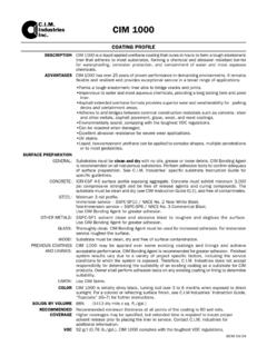
1 M. Features Novibra type M is specifically designed to give large de- flection at low loads. Although the mount design allows high deflection, the mountings are compact in weight and easy to install. Its unique construction and the latest production methods make Novibra type M a high performance antivibration mounting having a number of advantages: Tight tolerances on dynamic stiffness rate for accurate vibration calculations. Wide load rating options, 2500 kg. Corrosion protected to cope with arduous environ- Novibra type M ments on land or marine applications (Fe/Zn8C2 as Type M is ideal for applications involving isolation of low per ISO 2081). frequency vibrations in all planes. Also suitable for shock Clear and durable product marking so that mountings attenuation due to the designed ability to offer large de- can be identified even after several years in operation.
2 Flection. Provides passive vibration isolation on electronic instruments, measuring equipment and test cells. When using M mount together with the height adjuster HA, it is necessary to use a washer. The diameter of the Specific fields of application are: washer must be 20% larger than the diameter of the upper Compressors Electric motors plate (D). Refrigerators Weighing scales AC-units Test cell equipment Ventilators Noise control units Fans Pumps Powder handling machinery Food processing Vibratory screens equipment Packaging applications M 7, M 25, M 50, M 400, M 600, M 1500. M 100, M 200. D. G. d E. h d H A A. K K. Dimensions in mm Weight M-Max(kg). Type 40 IRH 60 IRH D E A K H h d G (kg) 40 IRH 60 IRH.
3 M 7 2255110 2255120 18 43 50 64 20 7 M 6 9. M 25 1861220 1861230 33 56 66 85 25 11 M 8 20 50. M 50 1861240 1861250 45 76 92 114 35 14 M 10 40 80. M 100 1861620 1861610 53 96 110 136 40 15 M 10 70 150. M 200 1861660 1861670 58 101 124 151 45 13 M 10 130 220. M 400 1861680 1861690 78 120 150 63 18 M 12 280 500. M 600 1533710 1533720 100 160 200 85 25 M 16 380 750. M 1500 1533730 1533740 186 250 310 160 43 M 24 1400 2500. 32 Trelleborg Industrial AVS operates a policy of continuous improvement and development. We reserve the right to change design and specification of our products without prior notification or alteration of literature M. Note: The natural frequencies and degrees of isolation are based on dynamic characteristics of the mountings.
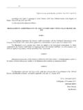
4 Load per mounting (kg). M25 M1500. 3000. Diagram 1 Diagram 2. 2500. 2000. M. 1500. 15. 00. 0. -6. -6. 00. 0. 15. 1000. M. M. 800. 15. 00. 700. 0. -4. -4. 0. 600. 00. 15. M. 500. M. 0. 60. 60 -6. 0- 00. 0- 60. 400. 6. M. M. M. 40. 40. 60. 300. M. 0- 0- 60. 40. 0. 40 -4. 0- 00. 200. 40 M 6. M. 40. 0- 60. 40. 150. M. M. 0- Load per mounting (kg). 20. 20. 0- M. M7. 60. 0. -4. M M2. 100 10. 0. M 0. 20. 6. 10 00. 0- 9. 0- -4. 10. 8. 60 0. 80. M. 70 7. 0. -6. 60. M. 6. 60. 50. 7- M. M. 7- 60. M. 10. 50. 50. 5. M. 0- -6. 40. 0. 0. 40. 40 4. -6. 25. 0- M. 10. M. 25. M. 30 3. -6. 0. 0. -4. M. 40. M. 50. 50. 7- 7- M. -4. 40. M. 20 2. 0. 0. -4. 15 25. M. M. 25. -4. 0. 10 1. 2 3 4 5 6 7 8 9 10 12 14 16 18 20 2 3 4 5 6 7 8 910 12 14 16 20 25 30 40 50.
5 Natural frequency (Hz) M7 A, M7 B 1 2 3 4 5. Interfering frequency (Hz) Static deflection (mm). 2. Diagram 3. 3 Re To select correct mounting, following son data are needed: 4 anc 1) Load per mounting (kg). 2) Interfering frequency (Hz). 5 e (Hz = rpm / 60 ). Select correct load line in diagram 1 and 6 correct interference line in diagram 3. 7. 8. Avo The load line intersects with required type of mounting. id t Connect this intersection point vertically 10 his down to the interference line in diagram 3. reg Here, on the sloping curve, the isolation ion degree is indicated. 15 For static deflection, see diagram 2. 20. 25 1 2. 30 0 L. 50. 40 70. 50 80. 60 85 3. I. 70 90. 80. 100. Degree of isolation (%).
6 Trelleborg Industrial AVS operates a policy of continuous improvement and development. We reserve the right to change design and specification of our products without prior notification or alteration of literature 33.