Transcription of INSTALLATION INSTRUCTIONS 01/26/10 “H” BEAM STEEL ...
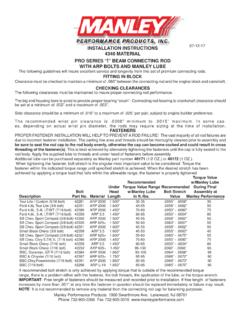
1 INSTALLATION INSTRUCTIONS 01/26/10 . H BEAM STEEL CONNECTING ROD. WITH ARP 8740 or 2000 BOLTS. Forged from 4340 chrome moly STEEL , fully machined and shot peened, Manley rods are designed for use in today's high performance engines. The following guidelines will insure service and longevity expected of this premium rod. FITTING IN BLOCK. A minimum of .060 clearance MUST be maintained between the connecting rod and the engine block or cam- shaft. If clearance problems exist between the connecting rod and engine block, it is highly recommended that the block be clearanced for the rod, not vice-versa, in order to maintain the structural integrity of the rod. CHECKING CLEARANCES. The following clearances MUST be maintained to insure proper connecting rod performance. The big end housing bore is sized to provide proper crush ; connecting rod bearing to crankshaft clearance should be set at .002 minimum to .003 maximum during assembly. Side clearances on both rods should be a minimum of.
2 015 to a maximum of .025 per pair. Recommended side clearances for the Ford and are .010 - .020 and .015 - .025 respectively per pair. (Actual side clearances are subject to variation based on personal preferences of the engine builder.). The recommended wrist pin clearance is .0008 minimum to .0015 maximum. In some cases, depending upon actual wrist pin diameter, this MAY NOT provide adequate clearance and may require sizing at the time of INSTALLATION . FASTENERS. PROPER FASTENER INSTALLATION WILL PREVENT ROD FAILURE!! Ninety percent of all rod failure are due to incorrect fastener INSTALLATION and/or maintenance. Fasteners supplied are as follows: Torque Value w/30wt. Oil Recommended During Final Torque Value Range Bolt Bolt Assembly At Bolt w/30wt. Oil Part No. Diam. Material Manley Performance Stretch In 42239 7/16 8740 90 ft. lbs..0059 - .0063 85 - 95. 42386 7/16 8740 80 ft. lbs..0050 - .0054 80 - 85. 42361 7/16 8740 80 ft. lbs..0052 - .0056 80 - 85.
3 42354 7/16 8740 95 ft. lbs..0050 - .0054 90 - 100. 42383 3/8 8740 55 ft. lbs..0047 - .0052 50 - 60. 42350 3/8 ARP 2000 60 ft. lbs..0058 - .0062 55 - 65. 42351 3/8 ARP 2000 65 ft. lbs..0058 - .0062 60 - 70. 42390 7/16 ARP 2000 90 ft. lbs..0050 - .0060 90 - 100. 42249 7/16 ARP 2000 95 ft. lbs..0060 - .0065 90 - 100. 42384 7/16 ARP 2000 95 ft. lbs..0064 - .0068 90 - 100. 42391 7/16 ARP 2000 105 ft. lbs..0069 - .0073 100 - 110. The parting line area and threads should be THOROUGHLY cleaned prior to assembly and be sure to seat the rod cap to the body of the rod evenly, otherwise the cap can become cocked and could result in cross threading of the fastener(s). This is best achieved by alternately tightening the fasteners until the cap is fully seated to the rod body. Fasteners MUST be submerged in 30 wt. oil or equivalent. Do not use moly or engine lube. Bolt stretch value should be checked against torque prior to INSTALLATION . DO NOT OVER TORQUE! IMPORTANT: Free length of fasteners should be measured and recorded prior to INSTALLATION .
4 If free length of fasteners increases by more than .001 at any time the fastener in question should be replaced immediately or failure may result. NOTE: It is not recommended to remove any material from the connecting rod cap for balancing purposes. Manley Performance Products 1960 Swarthmore Ave. Lakewood, NJ 08701. Phone 732-905-3366 Fax 732-905-3010