Transcription of H. Soyama, “Key Factors and Applications of Cavitation ...
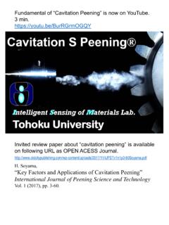
1 Fundamental of Cavitation Peening is now on YouTube. 3 min. Invited review paper about Cavitation peening is available on following URL as OPEN ACESS Journal. H. Soyama, Key Factors and Applications of Cavitation Peening . International Journal of Peening Science and Technology Vol. 1 (2017), pp. 3-60. Cavitation S Peening . S Shotless, Shockwave, Smooth, Soyama Cavitation S Peening is a peening method Cavitating Jet using Cavitation impacts in the same way as shot peening to improve fatigue strength and/or to introduce compressive residual stress.
2 The peening method using Cavitation Cavitation Impact impact is called Cavitation shotless peening (CSP) , as Shotless Shot shots are not required (see Fig. 1). In the case of Cavitation shotless peening, Cavitation is generated by cavitating jet. Fig. 1 Shotless peening and shot peening Cavitation is phase change phenomena from Bernoulli's equation liquid-phase to gas-phase. It is similar to boiling, v2. but, in the case of Cavitation , liquid-phase becomes p g z const . 2. gas-phase by decrease of static pressure until saturated vapor pressure due to increase of flow Head velocity (see Fig.)
3 2). When the static pressure is Static pressure Flow velocity increased by decrease of the flow velocity, the Cavitation bubble is collapsed. At the Cavitation Fig. 2 Phase diagram of water and Bernoulli's equation bubble collapse, a part of the bubble is deformed and a micro-jet is produced (see Fig. 3). As the In Water Cavitation bubble Shock wave speed of the micro-jet is about 1,500 m/s, the Micro-jet Rebound micro-jet produces plastic deformation pit on the solid surface. After the Cavitation bubble shrink, the Cavitation bubble rebounds.
4 At the rebound, shock Solid surface Plastic deformation wave is produced. The shock wave also produces [High speed/Low pressure region] [Low speed/High pressure region]. plastic deformation (see Fig. 3). Fig. 3 Schematic diagram of Cavitation bubble Cavitating jet is a jet with Cavitation bubbles produced by injecting a high-speed water jet into water (see Fig. 4). The Cavitation bubbles take place in the low pressure region of vortex core in the shear layer around the jet. The vortex cavitations combine and big Cavitation cloud is produced.
5 When the Cavitation cloud hit the surface, Cavitation impacts are produced at bubble collapses. Soyama successfully produced cavitating jet in air by injecting a high-speed water jet into a low-speed water jet. Nozzle Flow Schematic diagram Cavitating jet in water Cavitating jet in air*1. Fig. 4 Schematic diagram and photo of cavitating jet *1 , Trans. ASME, Journal of Fluids Engineering, Vol. 127, No. 4, 2005, pp. 1095-1101. [ ]. Improvement of Fatigue Strength . Cavitation S Peening improves the fatigue strength of gear made of carburized chromium molybdenum steel SCM420H*1.
6 It also enhances the fatigue strength of carburized chromium molybdenum SCM420*2 and SCM415*3, aluminum alloy AC4CH-T6*4, Duralumin, magnesium alloy, stainless steel, silicon manganese steel and other materials. 500 1000. a MPa SP2. CSP. 450 Cavitation SP1. Nm Peening Amplitude of bending stress 900. Dn 400. Not peened Torque Shot Peening 800. 350. Not peened 300 700. 105 106 107 104 105 106 107 108. Number of cycles to failure N Number of cycles to failure N. Fig. 5 Improvement of fatigue strength of gear Fig. 6 S-N curve of rotating bending fatigue demonstrated using a power circulating test (Carburized SCM420)*2.
7 Type gear tester (Carburized SCM420H)*1. 1000 200. a MPa a MPa 160. Amplitude of bending stress CSP. Amplitude of bending stress 900. CSP. 120 SP. 800 SP. Not peened Not peened 700 80. 104 105 106 107 108 105 106 107 108. Number of cycles to failure N Number of cycles to failure N. Fig. 7 S-N curve of rotating bending fatigue Fig. 8 S-N curve of rotating bending fatigue test (Carburized SCM415)*3 test (AC4CH-T6)*4. *1 and , Sustainable Surface Modification Using Cavitation Impact for Enhancing Fatigue Strength Demonstrated by a Power Circulating-Type Gear Tester, International Journal of Sustainable Engineering, Vol.
8 3, No. 1, 2010, pp. 25 - 32. *2 , Improvement of Fatigue Strength of Metallic Materials by Cavitation Shotless Peening, Metal Finishing News, Vol. 7, March issue, 2006, pp. 48 - 50. *3 and , Cavitation Shotless Peening for Improvement of Fatigue Strength of Carbonized Steel, . International Journal of Fatigue, Vol. 25, Nos. 9-11, 2006, pp. 1217 - 1222. *4 , , and , Cavitation Shotless Peening for Improvement of Fatigue Strength of Metallic Materials, Transaction of Society of Automotive Engineers of Japan, Vol. 34, No. 1, 2003, pp.
9 101 - 106. Intelligent Sensing of Materials Lab., Department of Nanomechanics, Tohoku University Peened Surface . Cavitation S Peening introduces compressive residual stress with a considerable less surface roughness compared to that from shot peening (see Figs. 9 and 10). Individual pit induced by Cavitation S Peening does not have sharp tip up around the pit, compared to a pit induced by ball indentation at nearly constant volume and depth (see Fig. 11). It is very shallow compared to the pit at constant depth of plastic deformation area (see Fig.)
10 12). 400. Residual stress MPa Not peened 0. -400. -800. SP. CSP. -1200. CSP (Ra = m) SP (Ra = m) 0 50 100 150 200. Fig. 9 Peened surface and residual stress (Ti-6Al-4V)* 5 Distance from the surface z m 200. Not peened Residual stress MPa 0. -200. CSP. -400. -600. SP. -800. -1000. CSP (Ra = m) SP (Ra = m) 0 20 40 60 80. Fig. 10 Peened surface and residual stress (SKD61)* 6 Distance from the surface z m h 450 m 480 m h'. 90 % 35 m 90 % 32 m Volume mm3 mm3. 400 m 400 m 40 m 40 m 400 m 400 m (a) CSP (b) Ball indentation Fig. 11 Aspect of pit*7 Fig.