Transcription of Ram Fuel Fill Tube Kit
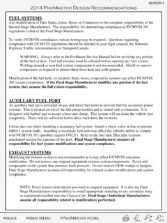
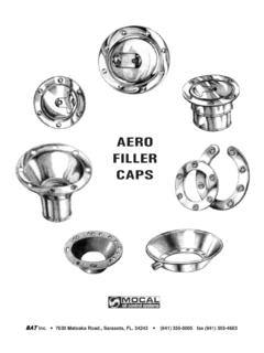
1 08/01/2013. 2014 Ram fuel Filler Pipe Location/Attachment Ram fuel fill Tube Kit The fuel filler kit contains braided protective sleeves to A fuel fill housing is included in box-off models and has help protect the fuel filler hose. If the braided protective been designed for easy installation (external flange sleeve must be cut to a shorter size, use a hot-knife or mounted) and to insure proper fuel tube fill angle of 37 . equivalent to cut the sleeve. This hot-knife process melts Included in the kit are installation instructions, various fill the ends of the nylon stand together preventing the sleeve and vapor hoses that can be cut and assembled per body from unraveling.
2 If a hot-knife is not available, use a applications, hose clamps, ground strap, and a hose tiestrap on the end that is cut to ensure the protective connector. A DIESEL or GAS fuel label will also be sleeve does not come unraveled. included depending on application. The part numbers for the kits are: Box Off Diesel: 52121252AA. Body Mount Guidelines for Ram (2500/3500). NOTE: See page below for urea h ose modifications Box Off Gas: 68312861AA. Chassis Cab: 5221693AD The following section shows suggested guidelines for Body Mounts for Ram 2500/3500 applications.
3 Installation Suggestions Caution: Use of proper safety equipment is recommended when performing any modification or Always mount the fuel fill housing as high as alterations. possible and route the fuel fill tube on a continuous downward slope (approx. 37 ) to These guidelines apply to second stage manufacturers insure good fuel fill quality. who mount a body to the Ram Pickup Truck. This applies to trucks which have been ordered from the factory with Mount the fuel fill tube upper with the vent tube at the box deleted or those where the factory installed box is the 9:00, 12:00 or 3:00 position.
4 Removed after delivery. When routing the vent tube, make sure there are The mounting location brackets on the chassis that are no dips or sags. It should have a downward slope used for the pickup bed mounting should be utilized for from the fuel filler tube upper to the fuel tank installing the new body. On the short bed there are vent nipple. Tie strap it to prevent any sags that six mounting location brackets and on the long bed may accumulate fuel in the hose. there are eight. Grade M12 Fasteners (or equivalent) should be Always connect the ground strap from the fuel fill used.
5 Torque to 60 + ft-lbs. upper to the frame. This is a must! If the ground With the body in position the gap between the body strap is not attached Electro static build up could mounting points and the chassis mounting brackets occur during refueling. should be minimized to assure that there is no distortion of the chassis mounting brackets when the When Mounting the fuel Filler and Hose Assembly body mounting fasteners are torqued to specification. directly to the Frame with Self Supporting Metal spacers are recommended in cases where the Structure as typically used.
6 On a Dump Body, it is gap exceeds 2 mm. recommended to use a minimum of 2 Angle or 2 . Square Tube for structure. Since the guidelines might not be appropriate for every application of a body installation, following the guidelines Attention: When installing Aux fuel fill hardware, listed above does not eliminate the responsibility of the or various body hardware, you must not trap second stage manufacturers to certify to compliance to debris, or water around the filler neck, fuel pump FMVSS and CMVSS standards. module, or rollover valve. Failure to do so can result in contaminated fuel leading to engine The final stage manufacturer who installs a second unit damage or performance loss.
7 Body on the chassis is responsible for compliance with (1) 2 3 (3)(4) (3). FMVSS/CMVSS 204 , 208 , 212 , 214 ,219 , and (3). Ensure that the upfitter installed body, or 301 Federal Regulations. Questions regarding components, do not trap water or debris on the top compliance with FMVSS/CMVSS regulations should be of tank or around fuel filler inlet. Be aware of, and directed to your legal counsel, the National Highway Traffic prevent attached components that may be Safety Administration, or Transport Canada. directing, or trapping, water or debris on fuel tank inlets or top surface.
8 If the final stage manufacturer modifies any portion of the fuel system, they assume the full system responsibility. + - Index Main Menu 2500/3500 Ram Home ALL IN OUT. 08/01/2013. 2014 Ram fuel Filler [Type the Pipe Location/Attachment document title]. 2013 and Newer Ram 2500/3500 Diesel Box-off Urea Filler Relocation Obtain Ram Chassis Cab Urea filler neck p/n 68101174AA. Remove the fill & vent hoses from the assembly, carefully not to damage the swedge ribs on the quick connect and the urea filler cup. Fabricate a bracket to hold the urea filler to meet the attachment requirements below.
9 Position the urea filler 30 from vertical. The vertical height between the urea tank inlet port and the urea filler cap need to be at least 10 inches. The small diameter recirculation vent port must be positioned between 9 & 3 o'clock. Replace the factory equipped pickup truck urea hoses with commercially available Tygon tubing. Insert quick connects into both the filler & vent Tygon hose, tighten the hose to the quick connects using the stainless steel clamps. Connect the hoses to the urea fill &. vent lines on the truck at the frame box bracket Route the hoses in an upward slope to the mounted urea filler, careful not to leave any sumps in the hose route.
10 Slide the stainless steel hose clamps on the hoses and push the hoses onto the urea filler. Confirm that the hose flows smoothly downhill and that there are no kinks or sumps in the hoses. Readjust if necessary and tighten the clamps. Add some urea to the tank and check for leaks. Install urea cap. + - Index Main Menu 2500/3500 Ram Home ALL IN OUT.