Transcription of THERMOWELL CALCULATIONS TO THE NEW ASME PTC 19.3 …
1 Temperature Controls Pty Ltd ACN: 075 298 592 ABN: 966 501 901 83 Sydney (Head Office): 7 Yamma St, Sefton, NSW 2162 Australia Ph: 61 2 9721 8644 Fax: 61 2 9738 9339 Melbourne: 8/280 Whitehall St, Yarraville VIC 3013 Australia Ph: 61 3 9687 0000 Fax: 61 3 9687 1900 Brisbane: 28a 121 125 Kerry Rd, Archerfield, QLD 4108 Australi Ph: 61 7 3373 8424 Fax: 61 7 3821 3693 W: E: 1661 ALL THERMOWELL CALCULATIONS TO THE NEW ASME PTC TW 2016 Thermowells are used to protect Thermocouples, RTD sensors and Bimetal Thermometers when measuring temperatures in high pressure or hostile corrosive applications in pipelines. Thermowells are machined from solid barstock materials which are suitable for the process medium and temperature, and supplied with a process connection, threaded, flanged or weld in to meet the specific installation requirements.
2 As the flow of the medium ( Fluid or Gas ) in the pipeline passes by the THERMOWELL it forms a turbulent wake ( known as Von Karman trail ) that generates a vibration in the THERMOWELL proportionate to the diameter of the THERMOWELL and velocity of the medium. The THERMOWELL must be constructed sufficiently rigid so that it s vibration frequency does not equal the frequency of the Von Karman trail, where the THERMOWELL would vibrate to the point of breaking off. The American Society of Mechanical Engineers ( ASME ) have developed a Performance Test Code ASME PTC TW-2016 for use to provide mathematical proof that the material chosen and the mechanical design will not fail given the effects of the operating conditions. The ASME PTC TW 2016 wake frequency calculation is used for one piece thermowells in tapered, straight or stepped stem designs from solid barstock materials, process connections include, weld in, Flanged, Threaded and Van Stone styles, all with a surface finish of um Ra or better.
3 To ensure compliance with this latest standard, Temperature Controls have implemented a computer program to perform wake frequency CALCULATIONS on barstock thermowells to ASME PTC TW 2016 verifying that the specified THERMOWELL dimensions are adequate to withstand the service conditions of temperature, pressure, velocity and vibration. Individual Tag number CALCULATIONS can be performed as part of a quotation for supply of thermowells with the customer providing the specific process data. A certificate of compliance is issued as part of our Quality Assurance documentation with order shipment. Support collars or velocity collars are used to support the stem inside the shielded length of a flange mount THERMOWELL to theoretically reduce the insertion length. The ASME 2016-TW standard does not support the use of velocity collars as the collars do not assure a rigid support plane and so the THERMOWELL stem will be subjected to a hammering effect brought on by the constant vibration.
4 Positioning of thermowells It is generally believed that a temperature element must be centred in the pipe, however in practice so long as the temperature sensor is within the middle third of the pipe there is no reason to expect any decrease in measuring accuracy. Thermowells that fail to meet pressure, stress or frequency requirements as per ASME PTC TW-2016 may be modified to reach a passable solution with modification to:- Material; an alternative material with increased mechanical properties. Insertion Length: Reducing the unsupported stem length will improve the force to natural frequency ratio. Tip Diameter: Increasing the tip diameter on a tapered stem THERMOWELL will improve the THERMOWELL strength, or change to a straight stem design. Fillet Radius: Increase the fillet radius to improve strength but consider the flange gasket face surface area.
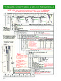
5 THERMOWELL CALCULATIONS TO ASME PTC TW 2016 Scope of ASME PTC TW-2016 Tapered and Straight Design Stepped Tip Design Sample Certificate Process Data Required for a calculation Process Medium : Gas or Liquid Type Velocity Viscosity Density Maximum Temperature Maximum Pressure Shielded Length Pipe Size / Schedule Not within the scope of ASME PTC Thermowells fabricated from pipe Special surface finish Knurled Thermowells with 2 or more piece welded stems Stems that include flame spray ( stellite )or weld overlay Ceramic or Non-metallic materials Design Input Minimum Maximum Minimum Maximum Unsupported Length U mm mm 127 mm mm Bore Diameter d mm mm mm mm Tip Diameter B mm mm mm Support Diameter A mm 80 mm Taper Ratio B/A 1 N/A N/A Minimum Wall Thickness mm mm Temperature Controls Pty Ltd ACN: 075 298 592 ABN: 966 501 901 83 Sydney (Head Office): 7 Yamma St, Sefton, NSW 2162 Australia Ph: 61 2 9721 8644 Fax: 61 2 9738 9339 Melbourne: 8/280 Whitehall St, Yarraville VIC 3013 Australia Ph: 61 3 9687 0000 Fax: 61 3 9687 1900 Brisbane: 28a 121 125 Kerry Rd, Archerfield, QLD 4108 Australia Ph: 61 7 3373 8424 Fax: 61 7 3821 3693 W: E: ASME PTC TW 2016 Process Data required for a calculation #1661/A Before we can prepare your calculation we need you to complete the table below.
6 Standard Answer Customer # Tag # Reference # Material THERMOWELL type Flange size / process fitting Flange penetration weld Partial (standard) Full penetration (recommended) Fillet (Root) R3 Standard (Option R5) Bore (d) = to Process medium gas or liquid Velocity m/s Viscosity cp Density kg/m Maximum design temperature Maximum design pressure Kpa Shielded length (Lo) (Flanged thermowells only) (includes standoff and pipe thickness) Pipe size / schedule (see attached) Overall Length (L) Unsupported length (U) to Lag Extensions (F) Stem Major - Root diameter (Q) to 80mm Stem Minor - Tip diameter (B) to Taper ratio B/A Tip thickness 6mm Note: Calculating pipe immersion = (L) (Lo) (F) = pipe immersion INSTRUMENTCONNECTIONMINORSTEMU(UNSUPPORT ED LENGTH)STDTIP THICKNESS (t)BORE (d)FILLET RADIUSSTD R3 OPTION R5 MINIMUM25mm(L)OVERALL LENGTH REQUIRED FOR CALCULATIONBLAGGING EXTENSION (F)FULL PENETRATION WELDPARTIAL PENETRATION WELD CONDITIONSSCALE : NTSSIZE : A4 DATE : 13/04/12 TITLEDRAWING BY CONTROLS PTY LTDSYDNEY : 7 YAMMA ST SEFTON , NSW 2162 PHONE : (02) 9721 8644 FAX.
7 (02) 9738 9339 THIS DRAWING IS OUREXCLUSIVE PROPERTYAND MUST NOT BECOPIED OR HANDEDTO ANY OTHER PARTIESWITH OUT WRITTENPERMISSION. IT SHALLBE RETURNED UPONREQUESTQ uality SystemQualityEndorsedCompanyCertificate No:QEC 14412AS/NZS 9001:2000 MELBOURNE : 8/280 Whitehall StYARRAVILLE VIC 3013 PHONE : (03) 9687 0000 FAX : (03) 9687 1900 EMAIL Size 150#300# 600#900 / 1,500#2,500#1 2 (F) 57mm57mm 80mm80mm90mmMATERIALFLANGED TAPER DESIGN BARSTOCK THERMOWELLSPECIFY SHIELDED LENGTH (Lo)(PIPE SIZE REQUIRED FOR CALCULATION)(INCLUDES STAND OFF AND PIPE THICKNESS)A (Q)STEMMAJORU(UNSUPPORTED LENGTH)STDTIP THICKNESS (t)BORE (d)FILLET RADIUSSTD R3 OPTION R5 MINIMUM25mm(L)OVERALL LENGTH REQUIRED FOR CALCULATIONBLAGGING EXTENSION (F)FULL PENETRATION WELDPARTIAL PENETRATION WELDR eport InformationCustomer:Temperature Controls (Sample copy)Date / Time:Tag Numbers:0 Reference #:Process Fluids:GasPipe Size / Schedule:6" STD Max Temperature (T) / Pressure (P).
8 60 C / 1960 KPaFluid Flow in^3/sFluid Velocity (v):30 m/sFluid Kg/m^3 Fluid centipoiseDensity (Pm) lb/in^3 Elastic Modulus, E(T):28300000 psiAllowable Stress (S) / Fatigue Limit (Sf):16700 psi/9100 psiIn-Line Reson. Velocity(VIR) m/sVon Mises Stress (Root) psiBending Stress at VIR ( ) psiDynamic Stress at V ( ) psiThermowell ConfigurationFrequency # (Re):46941 FlangedFrequency must be [Hz]Strouhal # (Ns) Natural Freq (fnc) [Hz]Scruton # (Nsc) Frequency (fs) [Hz]Freq Ratio (fs/fnc) " 150#Raised Face316/316 LAllowable Stem Pressure(Pc) Tip Pressure(Pt) 1441228/09/2011 10:45:07 AM0 Process Operating ConditionsStem Style: THERMOWELL Material PropertiesStressesVibrationProcess Connection: THERMOWELL Material:Flange Size l Rating:PressureFlange Facing:Flange Material:Bore Size:Overall Length (L): THERMOWELL RatingUnsupported Length (U):Shielded Length (Lo):Oscillating Stress (psi) Diameter (B):Fillet (Root):Frequency (Hz) Thickness (t):Steady-State Stress (psi) Diameter (Q).
9 Pressure (psi)SAI GlobalISO 9001 The THERMOWELL design has PASSED the wake frequency calculation These well design CALCULATIONS are based on the ASME power test code PTC formulas. The results of these CALCULATIONS should only be used as a guide for THERMOWELL design. Temperature Controls does not guarantee the performance of a specific well design obtained from the use of these CALCULATIONS .Printed using the V-MAC Wake Calc SystemNominal Pipe Size InchesNominal Pipe Size mmOD mmSchedule ANSI / ASME Wall thickness mmInternal Diameter 1 1 1/26573 STD/40 1/26573XS/80 1 1 SIZE / SCH FOR ASME PTC TW 2016 For calculation purposes When calculating sheilded length use 100mm for the Stand off plus pipe thicknessLine size 50mm = 2" STD, 100mm = 4" STD, 150mm = 6" STD, 200mm = 8" STD, 250mm = 10" STD & 300mm = 12" STD