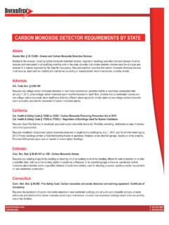
Transcription of Concentric Vent Installation Guide - DiversiTech
1 Concentric Vent Installation Guide4010793 Certified to ULC Std S636 GeneralThe Concentric Vent allows both the intake for combustion air and the exhaust vent to pass through a standard roof or sidewall. This is an alternative to the standard two pipe intake/vent shown in the basic furnace Installation instruc-tions. Follow these instructions as well as the basic furnace Installation instruction for Installation of the intake/vent pipe(s) and all furnace Installation procedures. Refer to the furnace Installation instructions for intake/vent pipe sizing information. NOTE: The Concentric Vent reduces the allowable intake/vent piping length by 5 feet from that listed in the basic furnace Installation kit contains the following parts:(1) Combustion Air Inlet Cap(1) Air Inlet Pipe(1) Vent Pipe(1) Intake/Vent Concentric Y Key Installation Requirements1.
2 Examine all components for possible shipping damage prior to Proper joint construction is essential for a safe Installation . Follow these instructions exactly as This venting system must be free to expand and contract. This venting system must be supported in accordance with these instructions. 4. Check for proper joint construction when joining pipe to Check for unrestricted vent movement through walls, ceilings, and roof penetrations. 2 Warningso Do not operate the furnace until the Installation and assembly of the Concentric Vent and all piping are completed. Failure to follow this warning could result in product damage or improper operation, personal injury or Different manufacturers have different joint systems and adhesives.
3 Do not mix pipe, fittings, or joining methods from different manufacturers. o Plastic venting systems shall not pass through rated fire Keep assembly free of insulation during installationo Do not use field supplied couplings to extend Recirculation of flue gasses may occur, causing the intake pipe to freeze shut during cold weather operation if the venting system is not installed per these guidelines. If the venting system is not installed properly, flue gas may recirculate, possibly causing the intake pipe to freeze shut during cold The safe operation of the vent system is based on the use of parts supplied in this kit or approved per the guidelines that follow in the instructions.
4 The performance of the system may be affected if the combination of these prescribed parts is not used in actual building ) Acceptable Gas Appliances, Components, Sealants and Installation Methods a) The DiversiTech Concentric vent termination kit is intended for use with Category IV high efficiency (condensing gas) furnaces or water heaters with exhaust temperatures up to and including 65 C (149 F), ULC S636 Class II. Failure to follow this warning could result in fire, personal injury or death. b) Pipe and fittings are required to complete Installation (user supplied).
5 The combustion air and vent pipe fittings must conform to ANSI and ASTM standards D1785, F891, D2665, D2241, D2661, or F628. Pipe cement and primer must conform to ASTM standards D2564 or D2235. 3 c) In Canada, construct all combustion air and vent pipes for this unit of CSA or ULC certified Schedule 40 PVC, PVC-DWV, or ABS-DWV pipe and pipe cement. d) Failure to use pipe, fittings or solvents as outlined above can result in unsafe conditions. i. For assembly of PVC piping, DiversiTech Pro-Weld PVC Cement (clear) is recommended. ii. Where primer is required (see Section 4: Solvent Cementing), DiversiTech Pro-Prime PVC Primer (purple) is recommended.
6 E) PVC solvent cements and all primers must not be used more than 3 years beyond the date of manufacture printed on the container. f) Where firestopping is required, Fireseal 814 (red) or equivalent is recommended. g) If the assembly is too short, the 2 pipes supplied in the kit may be replaced by using same diameter, field supplied SDR 26 PVC (D2241) pipe. Do not extend pipes with Schedule 40 PVC or couplings. The additional wall thickness will restrict combustion air and may cause operational problems. Do not extend air inlet pipe more than 60 (see Figure 7).
7 H) Acceptance of the vent system is dependent upon full compliance with these Installation instructions, CSA B149 and local building and fire ) Installation and Terminations General Installation Notes: a) Prior to Installation the authority having jurisdiction (such as gas inspection authority, municipal building department, fire department, fire prevention bureau, etc.) should be consulted to determine the need to obtain a permit. b) Follow the appliance manufacturer s Installation instructions, local Installation codes from the authority having jurisdiction. 4 c) The venting system shall terminate in accordance with the requirements of 2, Natural Gas and Propane Installation Code, or , Propane Storage and Handling Code, as applicable.
8 D) Follow the appliance manufacturer s Installation instructions for details on vent-to-appliance connections. e) It is required that means shall be provided for draining the condensate. The venting system must be sloped upwards not less than 20mm per 1,000mm from the appliance to the vent terminal in order to prevent the collection of condensate. Refer to the appliance manufacturer s Installation instructions for further details regarding condensate drain fittings. f) Insulation must not interfere with any necessary clearances. g) Follow guidelines set by local regulatory authorities or local building codes with regard to framing, boot or flashing requirements for ceiling, floor or roof penetrations made by the Concentric Vent kit and associated vent piping.
9 H) Provide support as close as reasonably possible to any fittings to alleviate excessive stress at joints and within the piping system as a whole. Supports, hangers and anchors should be suitable for use with plastic pipe. i) Horizontal runs of PVC pipe must be supported at intervals of no more than 5 feet unless otherwise specified by local regulatory codes, the local authority having jurisdiction, or the appliance manufacturer. j) Vertical runs of PVC pipe should be adequately supported at the first penetration in order to bear the weight of the vertical run. The pipe should be securely fastened to the support structure.
10 Additional supports should be utilized on the vertical run, but they must allow for movement due to expansion and contraction. 5 k) Utilize or steel strapping (or equivalent) fastened to the support structure to support PVC pipe runs. Framing nails or screws may be used to fasten the strapping to the support structure. VERTICAL ROOF MOUNTINGNOTE: Roof mounting is recommended as it allows less intake air contaminants and reduces ground-level exhaust. Multiple Concentric Vent kits may be installed vertically following the same clearances between vent outlets as shown in Figure 6.