Transcription of Classic Performance Products Disc Brake Power Steering
1 2015 Edition& Classic Performance Products , Brake Power Steering Installation,Technical & Troubleshooting GuideBrake & Power Steering Installation and Technical GuideClassic Performance Products , Inc. | The Industry's First Choice in Brake , Steering & Suspension Parts | @ 2015 Classic Performance Products , COPIES OR REPRODUCTIONS IN All OR IN PART OF THIS DOCUMENT MAY BE MADEWITHOUT WRITTEN CONSENT OF CPP EXCEPT IN THE EXPRESS USE FOR INSTALLING OR TROUBLESHOOTING CPP SUPPLIED PRODUCT. All RIGHTS RESERVED. LAST REVISED 9/13 Introduction and TipsRead these instructions carefully and completely before installing your kit! The steps within this guide should be followed in the order in which it is written. Here are a few guide lines to help ensure a safe Brake system:Follow the steps outlined in this guide to ensure that you will easily pinpoint any trouble spots in your brakes while installing and assembling the system.
2 This guide was created to help make your Brake install as trouble free as possible Follow these instructions and we are certain you will have a pleasurable experience with your upgrade. Add only new Brake fluid. Contaminated fluid can cause damage to the sensitive hydraulic Brake components, corrode components, and increases the chance of system failure. Even unused fluid that was opened at an earlier time should not be used. Brake fluid absorbs mois-ture from the air. This moisture lowers the boil-ing point of the fluid. DOT 4 & 5 Brake fluid has a higher boiling point than DOT 3 but a shorter service life. DOT 3 fluid should be flushed every 2 years, while Dot 4 & 5 Brake fluid should be flushed every year to ensure a safe working system. Cleanliness is very important. In order to keep the system clean and safe make sure you clean the fittings and surrounding area before opening any part of the Brake system.
3 Do not mix silicone based Brake fluid with con-ventional Brake fluid. DOT rated silicone Brake fluid is safe to use, but can not be completely removed from the system once it has been added. Silicone fluid will feel more spongy than conventional fluid. Silicone will cause the seals to swell differently than conventional fluid and lead to a shorter seal life. Silicone fluid will not absorb moisture. If there is any moisture in the Brake system it will boil at 212 ; this means the boiling point for the entire system is now 212 . Be sure to check for a minimum of 18" of vacuum prior to installing a vacuum booster . Engines with big Performance camshafts typi-cally do not have enough vacuum . If you do not have enough vacuum ask us about our electric vacuum pump and hydraulic assist booster as-semblies. If the booster is mounted lower than the intake manifold do not eliminate any loops from the vacuum lines.
4 These loops act as moisture and vapor traps. Check the vacuum lines for gas odor or the presence of moisture. Gas fumes can deteriorate the internal rubber components of the booster . Do not use petroleum-based solvents to clean Brake components. They will damage the rubber seals in the Brake system. Use only cleaning fluids specifically designed for brakes. They will not leave a residue when they dry. Do not use compressed air to dry Brake compo-nents, even filtered air may contain moisture or traces of oil. Check for cracked, leaking, or swollen lines. These are dangerous and must be replaced. Do not attempt to drive the vehicle until a firm Brake pedal is website is filled with technical stories, instruction sheets, and how-to's galore! All this information is avail-able to you 24 hours a day, 7 days a week. Give it a @WE ARE HERE TO HELP!
5 24 Hours a 7 Days a Week!TECH GUIDESINSTRUCTION SHEETSMAGAZINE STORIESETC.! OUR WEBSITE: Check out our blog Performance Products , Inc. | | | 378 E. Orangethorpe Avenue, Placentia CA 92870 Classic Performance Products , of ContentsIntroduction and Tips.. pg. 2 Why Change to Disc Brakes? .. pg. 3 Understanding the Valves .. pg. 4 Using the Right Master Cylinder.. pg. 5 Bolting the Parts Together.. pg. 6 Pedal Assembly.. pg. 6 Pedal Rod Adjustment .. pg. 6 Master Cylinder Bore Depth .. pg. 7 Mounting the Caliper .. pg. 7 Routing the Hard Lines.. pg. 7 Connecting the Hoses .. pg. 8 Adjusting the Parking Brake .. pg. 8 Bleeding the System .. pg. 9 Diagnosing Brake Problems ..pg. 11 Trouble Shooting the System..pg. 12-13 Power Steering Guide Power Steering Fluid ..pg. 13 Vibrations in Steering Wheel & Column.
6 Pg. 13 pressure Reduction ..pg. 14 Remote Reservoir Systems ..pg. 14 Connecting the Steering Shafts ..pg. 14 Fasteners ..pg. 15 New vs. Used vs. Rebuilt ..pg. 15 Getting it Up and Running..pg. 15 Speaking of the Column..pg. 15 V-Belt Systems ..pg. 15 Serpentine Systems ..pg. 15 Common Fitting Sizes ..pg. 16 Common Torque Specs..pg. 16 Rack & Pinion Pump Diagram ..pg. 16 Steering Boxes & Racks Spline Sizes..pg. 17 Steering Column Spline Sizes ..pg. 17 Determining Spline Size ..pg. 17U-Joint Phasing ..pg. 17 General Torque Specifications ..pg. 17 ADVANTAGE #1 Disc brakes offer a significant advantage over drum brakes in a number of areas, the most important being safety. ADVANTAGE #2 Disc brakes resist Brake fade better than drums brakes do. Heat causes the disc to grow wider between the Brake pads reducing the pedal travel before the pads start to engage the rotors.
7 Drums expand farther away from the shoes increas-ing the pedal travel before the shoes start to engage the drums. ADVANTAGE #3 Disc brakes work better than drums when wet. When disc brakes become wet, the large majority of the water is spun off the disc. Then more water is wiped off by the Brake pad. Very little water will remain on the rotor, and is quickly removed as the Brake pressure is increased. In a drum Brake set up, water can become trapped inside the drum and act as a lubricant between the drum and shoes. ADVANTAGE #4 Disc brakes are much safer during a stop. Drum brakes have a tendency to pull one way or the other. This pull varies as shoes wear, return springs fatigue from age, the pivot mechanisms wear, lubrication dries out, etc. ADVANTAGE #5 Ease of serviceability. Disc brakes are much easier to service than drum brakes. Still have questions?
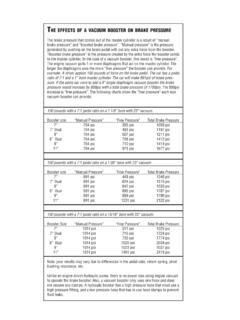
8 Give us a call, and a knowledge-able CPP customer service representative will be happy to assist ChANGE To DisC BrAkEs? Brake & Power Steering Installation and Technical GuideClassic Performance Products , Inc. | The Industry's First Choice in Brake , Steering & Suspension Parts | more pressure . Let s look at an example where the brakes are applied in a hard stop. The pressure will rise front and rear equally to about 500psi; after that the rear pressure will rise at about half the rate the front does. With 1000psi at the front brakes there will be about 750psi to the rear brakes. (The first 500psi is equal; increasing the front another 500psi will increase the rear 250psi.) Once the rear brakes reach their maximum pressure the front can continue to rise without the rear rising. Limiting the rear maximum pressure prevents the rear drums from being damaged by too much pressure and helps control rear wheel lock up.
9 The proportioning valves work together with the isolation valve. If the isolation valve cycles to prevent the front brakes from getting pressure , the proportioning and limiting functions will be bypassed. If the front brakes have failed there would be no need to balance the braking forces front to rear. UNDErsTANDiNG ThE VAlVEsResidual ValVesWhen setting up the Brake system make sure that the right valves are used. If the master cylinder reservoir is located lower than the wheel cylinders or calipers then you should have residual pressure valves. Use a 2psi valve for disc Brake calipers and 10psi valve for drum Brake wheel cylinders. The valve will maintain 2 or 10psi between the caliper/wheel cylinder and the valve. That is enough pressure to keep the Brake fluid from flowing back from the wheels and leaking past the reservoir vent and on to the ground.
10 The second function of the residual pressure is that there is a slight preload on the brakes keeping them at the ready. Combination ValVesThe combination valve is several valves in one. There is a Brake light warning switch and isolation valve, a metering valve for the front brakes, and a propor-tioning valve for the rear ValVesThe Brake light warning switch, also known as a pressure differential switch, is part of the isolation valve. The isolation valve is controlled by the front and rear incoming Brake pressure . The valve has incoming Brake pressure acting on each side of a piston. If the pressure on one side of the piston is more than the other side, the piston will start moving toward the lower pressure . At a predetermined point of piston movement the Brake light warning switch is triggered. If the pressure difference continues the piston will move far enough to completely stop fluid flow to the side with the lower pressure .