Transcription of Nuclear Power for Electrical Generation
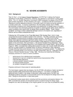
1 Reactor Concepts ManualNuclear Power for Electrical GenerationUSNRC Technical Training Center1-10703 NuclearPower forElectricalGenerationThe purpose of a Nuclear Power plant is not to produce or release Nuclear Power . The purpose of anuclear Power plant is to produce electricity. It should not be surprising, then, that a Nuclear Power planthas many similarities to other Electrical generating facilities. It should also be obvious that nuclearpower plants have some significant differences from other Concepts ManualNuclear Power for Electrical GenerationUSNRC Technical Training Center1-20703 FlangeStationary CoilRotorElectricalOutputGenerator HousingDrive ShaftELECTRICAL GENERATOROf the several known methods to produce electricity, by far the most practical for large scale productionand distribution involves the use of an Electrical generator.
2 In an Electrical generator, a magnet (rotor)revolves inside a coil of wire (stator), creating a flow of electrons inside the wire. This flow of electronsis called electricity. Some mechanical device (wind turbine, water turbine, steam turbine, diesel engine,etc.) must be available to provide the motive force for the Concepts ManualNuclear Power for Electrical GenerationUSNRC Technical Training Center1-30703 When a turbine is attached to the Electrical generator, the kinetic energy ( , motion) of the wind, fallingwater, or steam pushes against the fan-type blades of the turbine, causing the turbine, and therefore, theattached rotor of the Electrical generator, to spin and produce Concepts ManualNuclear Power for Electrical GenerationUSNRC Technical Training Center1-40703 HYDROELECTRIC PLANTELECTRICALGENERATORDAMWATERINLETVAL VEWATEROUTLETWATERTURBINEIn a hydroelectric Power plant, water, flowing from a higher level to a lower level, travels through themetal blades of a water turbine.
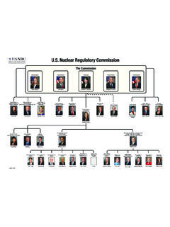
3 Causing the rotor of the Electrical generator to spin and Concepts ManualNuclear Power for Electrical GenerationUSNRC Technical Training Center1-50703 MainCondenserMainTurbineElectricGenerato rThrottleValveFeedwaterPumpABCDEFFuelSup plyBoilerFOSSIL FUEL STEAM PLANTIn a fossil-fueled Power plant, heat, from the burning of coal, oil, or natural gas, converts (boils) waterinto steam (A), which is piped to the turbine (B). In the turbine, the steam passes through the blades,which spins the Electrical generator (C), resulting in a flow of electricity. After leaving the turbine, thesteam is converted (condensed) back into water in the condenser (D). The water is then pumped (E)back to the boiler (F) to be reheated and converted back into Concepts ManualNuclear Power for Electrical GenerationUSNRC Technical Training Center1-60703 MainCondenserMainTurbineElectricGenerato rNuclearSteamSupplySystemThrottleValveFe edwaterPumpNuclear Fuel Steam PlantIn a Nuclear Power plant, many of the components are similar to those in a fossil-fueled plant, except thatthe steam boiler is replaced by a Nuclear Steam Supply System (NSSS).
4 The NSSS consists of a nuclearreactor and all of the components necessary to produce high pressure steam, which will be used to turnthe turbine for the Electrical Concepts ManualNuclear Power for Electrical GenerationUSNRC Technical Training Center1-70703 FissionLike a fossil-fueled plant, a Nuclear Power plant boils water to produce electricity. Unlike a fossil-fueledplant, the Nuclear plant s energy does not come from the combustion of fuel, but from the fissioning(splitting) of fuel Concepts ManualNuclear Power for Electrical GenerationUSNRC Technical Training Center1-80703 ENRICHMENT(% U-235)Uranium Ore ( ) Fuel Pellet ( )The most common fuel for the Electrical producing reactor plants in the United States is uranium.
5 Theuranium starts out as ore, and contains a very low percentage (or low enrichment) of the desired atoms(U-235). The U-235 is a more desirable atom for fuel, because it is easier to cause the U-235 atoms tofission (split) than the much more abundant U-238 atoms. Therefore, the fuel fabrication processincludes steps to increase the number of U-235 atoms in relation to the number of U-238 atoms(enrichment process).Reactor Concepts ManualNuclear Power for Electrical GenerationUSNRC Technical Training Center1-90703 CHEMICAL CONVERSION TO UF6 ENRICHMENTPELLETIZINGROD LOADINGBUNDLE ASSEMBLYBUNDLE FINAL INSPECTIONPACKAGING & SHIPPINGSITE INSPECTION & CHANNELINGT ubing & End PlugsSpacers & Tie PlatesOnce the fuel has been enriched, it is fabricated into ceramic pellets.
6 The pellets are stacked into 12-footlong, slender metal tubes, generally made of a zirconium alloy. The tube is called the fuel cladding. When a tube is filled with the uranium pellets, it is pressurized with helium gas, and plugs are installedand welded to seal the tube. The filled rod is called a fuel rod. The fuel rods are bundled together into fuel assemblies or fuel elements. The completed assemblies are now ready to be shipped to the plantfor installation into the reactor Concepts ManualNuclear Power for Electrical GenerationUSNRC Technical Training Center1-100703 REACTOR FUEL ASSEMBLIESBoth boiling water reactor and pressurized water reactor fuel assemblies consist of the same majorcomponents. These major components are the fuel rods, the spacer grids, and the upper and lower endfittings.
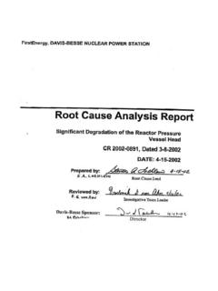
7 The fuel assembly drawing on page 1-11 shows these major components (pressurized waterreactor fuel assembly).The fuel rods contain the ceramic fuel pellets. The fuel rods are approximately 12 feet long and containa space at the top for the collection of any gases that are produced by the fission process. These rods arearranged in a square matrix ranging from 17 x 17 for pressurized water reactors to 8 x 8 for boiling spacer grids separate the individual rods with pieces of sprung metal. This provides the rigidity ofthe assemblies and allows the coolant to flow freely up through the assemblies and around the fuel spacer grids may have flow mixing vanes that are used to promote mixing of the coolant as itflows around and though the fuel upper and lower end fittings serve as the upper and lower structural elements of the assemblies.
8 Thelower fitting (or bottom nozzle) will direct the coolant flow to the assembly through several small holesmachined into the fitting. There are also holes drilled in the upper fitting to allow the coolant flow toexit the fuel assembly. The upper end fitting will also have a connecting point for the refuelingequipment to attach for the moving of the fuel with a pressurized water reactor fuel, there will also be guide tubes in which the control rods travel. Theguide tubes will be welded to the spacer grids and attached to the upper and lower end fittings. Theguide tubes provide a channel for the movement of the control rods and provide for support of the upper end of the control rod will be attached to a drive shaft, which will be used to position the rodduring brief description and a picture of boiling water reactor fuel can be found in Chapter3 (pages 3-3 and3-7).
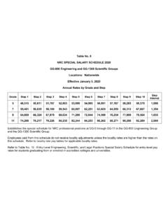
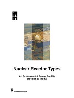
9 Reactor Concepts ManualNuclear Power for Electrical GenerationUSNRC Technical Training Center1-110703 ROD CLUSTER CONTROLTOP NOZZLECONTROL RODGRIDHOLD DOWN SPRINGFUEL RODTHIMBLE TUBEMIXING VANESDASHPOT REGIONDIMPLEBULGE JOINTSGRID SPRINGBOTTOM NOZZLETHIMBLE SCREW Reactor Concepts ManualNuclear Power for Electrical GenerationUSNRC Technical Training Center1-120703At the Nuclear Power plant, the fuel assemblies are inserted vertically into the reactor vessel (a large steeltank filled with water with a removable top). The fuel is placed in a precise grid pattern known as the reactor core. Reactor Concepts ManualNuclear Power for Electrical GenerationUSNRC Technical Training Center1-130703 Jet PumpReactorVesselSteamLineSteam Dryer&MoistureSeparatorReactor CoreRecirculationPumpThrottleValveElectr icalGeneratorTurbineCondenserPumpContain ment Suppression ChamberTurbine BuildingTo/FromRiverContainment/DrywellT here are two basic types of reactor plants being used in the United States to produce electricity, theboiling water reactor (BWR) and the pressurized water reactor (PWR).
10 The boiling water reactoroperates in essentially the same way as a fossil-fueled generating plant. Inside the reactor vessel, asteam/water mixture is produced when very pure water (reactor coolant) moves upward through the coreabsorbing heat. The major difference in the operation of a boiling water reactor as compared to othernuclear systems is the steam void formation in the core. The steam/water mixture leaves the top of thecore and enters two stages of moisture separation, where water droplets are removed before the steamis allowed to enter the steam line. The steam line, in turn, directs the steam to the main turbine, causingit to turn the turbine and the attached Electrical generator. The unused steam is exhausted to thecondenser where it is condensed into water.