Transcription of C S Chapter 7- Memory System Design DA 2/e
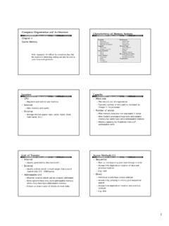
1 S2/eCDAC omputer Systems Design and Architecture Second Edition 2004 Prentice HallChapter 7- Memory System Design Introduction RAM structure: Cells and Chips Memory boards and modules Two-level Memory hierarchy The cache Virtual Memory The Memory as a sub- System of the computerS2/eCDAC omputer Systems Design and Architecture Second Edition 2004 Prentice HallIntroductionSo far, we ve treated Memory as an array of words limited insizeonly by the number of address bits. Life is seldom so world issues arise: cost speed size power consumption volatility other issues can you think of that will influence memorydesign?S2/eCDAC omputer Systems Design and Architecture Second Edition 2004 Prentice HallIn This Chapter we will cover Memory components: RAM Memory cells and cell arrays Static RAM more expensive, but less complex Tree and Matrix decoders needed for large RAM chips Dynamic RAM less expensive, but needs refreshing Chip organization Timing Commercial RAM products" SDRAM and DDR RAM ROM Read only Memory Memory Boards Arrays of chips give more addresses and/or wider words 2-D and 3-D chip arrays Memory Modules Large systems can benefit by partitioning Memory for separate access by System components fast access to multiple words more S2/eCDAC omputer Systems Design and Architecture Second Edition 2004 Prentice HallIn This Chapter we will also cover The Memory hierarchy: from fast and expensive to slow and cheap Example.
2 Registers->Cache >Main Memory ->Disk At first, consider just two adjacent levels in the hierarchy The Cache: High speed and expensive Kinds: Direct mapped, associative, set associative Virtual Memory makes the hierarchy transparent Translate the address from CPU s logical address to thephysical address where the information is actually stored Memory management - how to move information back and forth Multiprogramming - what to do while we wait The TLB helps in speeding the address translation process Will discuss temporal and spatial locality as basis for success ofcache and virtual Memory techniques. Overall consideration of the Memory as a Systems Design and Architecture Second Edition 2004 Prentice HallFig. The CPU Main Memory InterfaceSequence of events:Read:1. CPU loads MAR, issues Read, and REQUEST2. Main Memory transmits words to MDR3. Main Memory asserts :1. CPU loads MAR and MDR, asserts Write, and REQUEST2.
3 Value in MDR is written into address in Main Memory asserts Systems Design and Architecture Second Edition 2004 Prentice HallThe CPU Main Memory Interface - cont' points: if b<w, Main Memory must make w/b b-bit transfers. some CPUs allow reading and writing of word sizes < : Intel 8088: m=20, w=16,s=b= and 16-bit values can be read and written If Memory is sufficiently fast, or if its response is predictable,then COMPLETE may be omitted. Some systems use separate R and W lines, and omit Systems Design and Architecture Second Edition 2004 Prentice HallTable Some Memory PropertiesSymbol 601wCPU Word Size16bits16bits64 bitsmBits in a logical Memory address20 bits20 bits32 bitssBits in smallest addressable unit888bData Bus size816642mMemory wd capacity, s-sized wds2202202322mxsMemory bit capacity220x8220x8232x8S2/eCDAC omputer Systems Design and Architecture Second Edition 2004 Prentice HallBig-Endian and Little-EndianStorageWhen data types having a word size larger than the smallestaddressable unit are stored in Memory the question arises, Is the least significant part of the word stored at thelowest address (little Endian, little end first) or is the most significant part of the word stored at thelowest address (big Endian, big end first) ?
4 Example: The hexadecimal 16-bit number ABCDH, stored at address 0:ABCDmsb .. lsbABCD01 ABCD01 Little EndianBig EndianS2/eCDAC omputer Systems Design and Architecture Second Edition 2004 Prentice HallTable Memory PerformanceParametersSymbolDefinitionUni tsMeaningtaAccess timetimeTime to access a Memory wordtcCycle timetimeTime from start of access to start of next accesskBlock sizewordsNumber of words per blockbBandwidthwords/timeWord transmission ratetlLatencytimeTime to access first word of a sequence of wordstbl =Block timeTime to access an entire block of wordstl + k/baccess time (Information is often stored and moved in blocks at the cache and disk level.)S2/eCDAC omputer Systems Design and Architecture Second Edition 2004 Prentice HallCompo-nentAccessRandom Random Random Direct SequentialCapa- 64-1024+8KB-8MB 64MB-2GB 8GB 1 TBcity, 10ms 10ms-10sBlock1 word16 words16 words 4KB 4 KBsizeBand-SystemSystem10-4000 50MB/s 1MB/swidthclock ClockMB/sRaterate-80MB/sCost/MB High$10$.
5 25 $ $ The Memory Hierarchy, Cost, andPerformanceCPUC acheMain MemoryDisk MemoryTapeMemorySomeTypicalValues: As of 2003-4. They go out of date Systems Design and Architecture Second Edition 2004 Prentice HallFig. Memory Cells - a conceptual viewSelectDataInDataOutR/W SelectDataOutDataInR/WRegardless of the technology, all RAM Memory cells must providethese four functions: Select, DataIn, DataOut, and static RAM cell is will discuss more practical designs Systems Design and Architecture Second Edition 2004 Prentice HallFig. An 8-bit register as a 1D RAM arrayThe entire register is selected with one select line, and uses one R/W lineData bus is bi-directional, and buffered. (Why?)S2/eCDAC omputer Systems Design and Architecture Second Edition 2004 Prentice HallFig. A 4x8 2D Memory Cell ArrayR/W is commonto 8-bit buffered data bus2-4 line decoder selects one of the four 8-bit arraysS2/eCDAC omputer Systems Design and Architecture Second Edition 2004 Prentice HallFig.
6 A 64Kx1 bit static RAM (SRAM) chip~square array fits IC Design paradigmSelecting rows separatelyfrom columns means only256x2=512 circuit elementsinstead of 65536 circuitelements!CS, Chip Select, allows chips in arrays tobe selected individuallyThis chip requires 21 pins including power and ground, and sowill fit in a 22 pin Systems Design and Architecture Second Edition 2004 Prentice HallFig A 16Kx4 SRAM ChipThere is little differencebetween this chip andthe previous one, exceptthat there are 4, 64-1 Multiplexers instead of 1,256-1 chip requires 24 pins including power and ground, and so will require a 24pin pkg. Package size and pin count can dominate chip Systems Design and Architecture Second Edition 2004 Prentice HallFig Matrix and Tree Decoders3-to-8 line tree decoder constructedfrom 2-input line matrix decoderconstructed from 2-input gates. 2-level decoders are limited in size because of gate technologies limit fanin to ~8.
7 When decoders must be built with fanin >8, then additional levels of gates are required. Tree and Matrix decoders are two ways to Design decoders with large fanin:S2/eCDAC omputer Systems Design and Architecture Second Edition 2004 Prentice HallFig A 6 Transistor static RAM cellThis is a more practicaldesign than the 8-gatedesign shown value is read byprecharging the bitlines to a value 1/2way between a 0 anda 1, while asserting theword line. This allows thelatch to drive the bit linesto the value stored inthe Systems Design and Architecture Second Edition 2004 Prentice HallFigs Static RAM Read TimingAccess time from Address the time required of the RAM array to decode theaddress and provide value to the data Systems Design and Architecture Second Edition 2004 Prentice HallFigs Static RAM Write TimingWrite time the time the data must be held valid in order to decode address andstore value in Memory Systems Design and Architecture Second Edition 2004 Prentice HallFig A DynamicRAM (DRAM) CellWrite: place value on bit lineand assert word.
8 Precharge bit line,assert word line, sense valueon bit line with willdischarge in capacitor by reading(sensing) value on bit line, need to refresh thestorage cells of dynamicRAM chips complicatesDRAM System Systems Design and Architecture Second Edition 2004 Prentice HallFig DRAM Chiporganization Addresses are time-multiplexed on address bususing RAS and CAS asstrobes of rows andcolumns. CAS is normally used asthe CS pin counts: Without address multiplexing:27 pins including power andground. With address multiplexing: 17pins including power Systems Design and Architecture Second Edition 2004 Prentice HallFigs , DRAM Read and Write cyclesMemoryAddressRASD atatACAStPrechgRow AddrCol AddrtCR/WtRASM emoryAddressRASD atatDHRCASP rechgRow AddrCol AddrtCWtRAST ypical DRAM Read operationTypical DRAM Write operationAccess time Cycle timeNotice that it is the bit line prechargeoperation that causes the differencebetween access time and cycle hold from Systems Design and Architecture Second Edition 2004 Prentice HallDRAM Refresh and row access Refresh is usually accomplished by a RAS-only cycle.
9 The row address is placed on the address lines and RAS asserted. This refreshed the entire is not asserted. The absence of a CAS phase signals the chip that a row refresh is requested, and thus no data is placed on the external data lines. Many chips use CAS before RAS to signal a refresh. The chip has an internalcounter, and whenever CAS is asserted before RAS, it is a signal to refresh the rowpointed to by the counter, and to increment the counter. Most DRAM vendors also supply one-chip DRAM controllers that encapsulatethe refresh and other functions. Page mode, nibble mode, and static column mode allow rapid access tothe entire row that has been read into the column latches. Video RAMS, VRAMS, clock an entire row into a shift register where it canbe rapidly read out, bit by bit, for Systems Design and Architecture Second Edition 2004 Prentice HallFig A CMOS ROM ChipRowDecoderAddressCS+V2-D CMOS ROM Chip101000S2/eCDAC omputer Systems Design and Architecture Second Edition 2004 Prentice HallTbl Kinds of ROMROM TypeCostProgrammabilityTime to programTime to eraseMask pro-VeryAt the factoryWeeks (turn around)N/AgrammedinexpensivePROMI nexpensiveOnce, by endSecondsN/AuserEPROMM oderateMany timesSeconds20 minutesFlashExpensiveMany times100 , largeEPROM blockEEPROMVeryMany times100 ms,expensivebyteS2/eCDAC omputer Systems Design and Architecture Second Edition 2004 Prentice HallMemory boards and modules There is a need for memories that are larger and wider than a single chip Chips can be organized into boards.
10 Boards may not be actual, physical boards, but may consist of structured chip arrays present on the motherboard. A board or collection of boards make up a Memory module. Memory modules: Satisfy the processor main Memory interface requirements May have DRAM refresh capability May expand the total main Memory capacity May be interleaved to provide faster access to blocks of Systems Design and Architecture Second Edition 2004 Prentice HallFig General structure of Memory chipAddressDecoderMemoryCellArrayI/OMult iplexermAddressChip SelectssDataR/WsssCSAddressR/WDatamsThis is a slightly different view of the Memory chip than data chip selects ease the assembly ofchips into chip arrays. Usually providedby an external AND Systems Design and Architecture Second Edition 2004 Prentice HallFig Word Assembly from Narrow ChipsCSAddressR/WDataCSAddressR/WDataCSA ddressR/WDataSelectAddressR/Wsssp sAll chips have common CS, R/W, and Address chips expand word size from s bits to p x s Systems Design and Architecture Second Edition 2004 Prentice HallFig Increasing the Number of Words by aFactor of 2kThe additional k address bits are used to select one of 2k chips,each one of which has 2m words.