Transcription of Si5351A/B/C Data Sheet
1 Preliminary Rev. 8/11 Copyright 2011 by Silicon LaboratoriesSi5351A/B/CThis information applies to a product under development. Its characteristics and specifications are subject to change without ANY-FREQUENCY CMOS CLOCK GENERATOR + VCXOF eaturesApplicationsDescriptionThe Si5351 is an I2C configurable clock generator that is ideally suited for replacingcrystals, crystal oscillators, VCXOs, phase-locked loops (PLLs), and fanout buffers incost-sensitive applications. Based on a PLL/VCXO + high resolution MultiSynth fractionaldivider architecture, the Si5351 can generate any frequency up to 160 MHz on each of itsoutputs with 0 ppm error. Three versions of the Si5351 are available to meet a widevariety of applications. The si5351a generates up to 8 free-running clocks using aninternal oscillator for replacing crystals and crystal oscillators. The Si5351B adds aninternal VCXO and provides the flexibility to replace both free-running clocks andsynchronous clocks.
2 The Si5351B eliminates the need for higher cost, custom pullablecrystals while providing reliable operation over a wide tuning range. The Si5351C offersthe same flexibility but synchronizes to an external reference clock (CLKIN).Functional Block Diagram Generates up to 8 non-integer-related frequencies from 8 kHz to 160 MHz I2C user definable configuration Exact frequency synthesis at each output (0 ppm error) Highly linear VCXO Optional clock input (CLKIN) Low output period jitter: 100 ps pp Configurable spread spectrum selectable at each output Operates from a low-cost, fixed frequency crystal: 25 or 27 MHz Supports static phase offset Programmable rise/fall time control Glitchless frequency changes Separate voltage supply pins: Core VDD: or V Output VDDO: , , or V Excellent PSRR eliminates external power supply filtering Very low power consumption Adjustable output-output delay Available in 3 packages types: 10-MSOP: 3 outputs 24-QSOP: 8 outputs 20-QFN (4x4 mm).
3 8 outputs PCIE Gen 1 compliant Supports HCSL compatible swing HDTV, DVD/Blu-ray, set-top box Audio/video equipment, gaming Printers, scanners, projectors Residential gateways Networking/communication Servers, storage XO replacementSi5351 AMulti Synth NN = 2 or 7I2 CSSENOEBM ulti Synth 0 Multi Synth 1Si5351 BPLLVCVCXOI2 CSSENOEBM ulti Synth 0 Multi Synth 1 Multi Synth 2 Multi Synth 3 Multi Synth 4 Multi Synth 5 Multi Synth 6 Multi Synth 7Si5351 CPLLACLKINPLLBI2 CINTROEBM ulti Synth 0 Multi Synth 1 Multi Synth 2 Multi Synth 3 Multi Synth 4 Multi Synth 5 Multi Synth 6 Multi Synth 7 XAXBOSCXAXBOSCPLLBPLLAXAXBOSCO rdering Information:See page 6610-MSOP24-QSOP20-QFNSi5351A/B/C2 Preliminary Rev. Rev. OF CONTENTSS ectionPage1. Electrical Specifications .. 42. Detailed Block Diagrams ..93. Functional Description .. Input Stage .. Synthesis Stages .. Output Stage .. Spread Spectrum .. Control Pins (OEB, SSEN).
4 134. I2C Interface .. 145. Configuring the Si5351 .. Writing a Custom Configuration to RAM .. Si5351 Application Examples .. Replacing Crystals and Crystal Oscillators .. Replacing Crystals, Crystal Oscillators, and VCXOs .. Replacing Crystals, Crystal Oscillators, and PLLs .. Replacing a Crystal with a Clock .. HCSL Compatible Outputs .. 206. Design Considerations .. Power Supply Decoupling/Filtering .. Power Supply Sequencing .. External Crystal .. External Crystal Load Capacitors .. Unused Pins .. Trace Characteristics .. 227. Register Map Summary .. 238. Register Descriptions ..259. si5351a Pin Descriptions (20-Pin QFN, 24-Pin QSOP) .. 6210. Si5351B Pin Descriptions (20-Pin QFN, 24-Pin QSOP) .. 6311. Si5351C Pin Descriptions (20-Pin QFN, 24-Pin QSOP) .. 6412. si5351a Pin Descriptions (10-Pin MSOP) .. 6513. Ordering Information ..6614. Package Outline (24-Pin QSOP).
5 6715. Package Outline (20-Pin QFN) .. 6816. Package Outline (10-Pin MSOP) .. 69 Document Change List ..70 Contact Information .. 72Si5351A/B/C4 Preliminary Rev. Electrical SpecificationsTable 1. Recommended Operating ConditionsParameterSymbolTest ConditionMinTypMaxUnitAmbient TemperatureTA 402585 CCore Supply Buffer :All minimum and maximum specifications are guaranteed and apply across the recommended operating conditions. Typical values apply at nominal supply voltages and an operating temperature of 25 C unless otherwise and VDDOx can be operated at independent supply sequencing for VDD and VDDOx requires that both voltage rails are powered at the same 2. DC Characteristics(VDD= V 10%, or V 10%, TA= 40 to 85 C)ParameterSymbolTest ConditionMinTypMaxUnitCore Supply CurrentIDDE nabled 3 outputs 2235mAEnabled 8 outputs 2745mAPower Down (PDN = VDD) 20 AOutput Buffer Supply Current (Per Output)*IDDOxCL=5pF Current ICLKINCLKIN, SDA, SCLVin < V 10 AIVCVC 30 AOutput ImpedanceZO8 mA output drive current.
6 See "6. Design Consider-ations" on page 21. 85 *Note: Output clocks less than or equal to 100 Rev. 3. AC Characteristics(VDD= V 10%, or V 10%, TA= 40 to 85 C)ParameterSymbolTest ConditionMinTypMaxUnitPower-up TimeTRDYFrom VDD=VDDmin to valid output clock, CL=5pF, fCLKn>1 MHz 110msOutput Enable TimeTOEFrom OEB pulled low to valid clock output, CL=5pF, fCLKn>1 MHz 10 sOutput Phase OffsetPSTEP 333 ps/stepSpread Spectrum Frequency DeviationSSDEVDown spread spread Spectrum Modulation Specifications (Si5351B only)VCXO Control Voltage RangeVc0 VDD/2 VDDVVCXO Gain (configurable)KvVc = 10 90% of VDD, VDD = V18 150ppm/VVCXO Control Voltage LinearityKVLVc = 10 90% of VDD 5 +5%VCXO Pull Range (configurable)PRVDD = V* 300 240ppmVCXO Modulation Bandwidth 10 kHz*Note: Contact Silicon Labs for V VCXO 4. Input Clock Characteristics(VDD= V 10%, or V 10%, TA= 40 to 85 C)ParameterSymbolTest ConditionMinTypMaxUnitsCLKIN Input Low VoltageVIL x VDDVCLKIN Input High Voltage x VDD VCLKIN Frequency RangefCLKIN10 100 MHzSi5351A/B/C6 Preliminary Rev.
7 5. Output Clock Characteristics(VDD= V 10%, or V 10%, TA= 40 to 85 C)ParameterSymbolTest ConditionMinTypMaxUnitsFrequency 160 MHzLoad CapacitanceCL 515pFDuty CycleDCMeasured at VDD/2, fCLK=50 MHz455055%Rise/Fall Timetr20% 80%, CL=5pF,Drive Strength = 8 High VoltageVOHCL=5pFVDD VOutput Low VoltageVOL JitterJPERM easured over 10k cycles 35100ps pk-pkPeriod Jitter VCXO JPER_VCXO 60110ps pk-pkCycle-to-Cycle JitterJCCM easured over 10k cycles 3090ps pkCycle-to-Cycle Jitter VCXOJCC_VCXO 5095ps pkRMS Phase JitterJRMS12 kHz 20 MHz rmsRMS Phase Jitter VCXO JRMS_VCXO rmsTable 6. Crystal Requirements1,2 ParameterSymbolMinTypMaxUnitCrystal FrequencyfXTAL25 27 MHzLoad Capacitance CL6 12pFEquivalent Series ResistancerESR 150 Crystal Max Drive LeveldL 100 which require load capacitances of 6, 8, or 10 pF should use the device s internal load capacitance for optimum performance. See register 183 bits 7:6. A crystal with a 12 pF load capacitance requirement should use a combination of the internal 10 pF load capacitors in addition to external 2 pF load capacitors.
8 2. Refer to AN551: Crystal Selection Guide for more Rev. 7. I2C Specifications (SCL,SDA)1 ParameterSymbolTest ConditionStandard Mode100 kbpsFast Mode400 kbpsUnitMinMaxMinMaxLOW Level Input VoltageVILI2C x VDDI2C x VDDI2C2 VHIGH Level Input x x of Schmitt Trigger InputsVHYS VLOW Level Output Voltage (open drain or open collector) at 3 mA Sink CurrentVOLI2C2 VDDI2C2= V0 0 V x VDDI2 CVInput Current III2C 10 10 10 10 ACapacitance for Each I/O PinCII2C VIN= to VDDI2C 4 4pFI2C Bus TimeoutTTOT imeout Enabled25352535 to NXP s UM10204 I2C-bus specification and user manual, revision 03, for further details, go to: Only I2C pullup voltages (VDDI2C) of to V are 8. Thermal CharacteristicsParameterSymbolTest ConditionPackageValueUnitThermal Resistance Junction to Ambient JAStill Air10-MSOP131 C/W24-QSOP80 C/W20-QFN51 C/WThermal Resistance Junction to Case JCStill Air10-MSOP43 C/W24-QSOP31 C/W20-QFN16 C/WSi5351A/B/C8 Preliminary Rev.
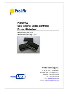
9 9. Absolute Maximum Ratings1 ParameterSymbolTest ConditionValueUnitDC Supply VoltageVDD_max to VoltageVIN_CLKINCLKIN, SCL, SDA to to (VDD+ )VVIN_XA/BPins XA, XB to VVJunction TemperatureTJ 55 to 150 CSoldering Temperature (Pb-free profile)2 TPEAK260 CSoldering Temperature Time at TPEAK (Pb-free profile)2 TP20 40 device damage may occur if the absolute maximum ratings are exceeded. Functional operation should be restricted to the conditions as specified in the operational sections of this data Sheet . Exposure to absolute maximum rating conditions for extended periods may affect device The device is compliant with JEDEC Rev. Detailed Block DiagramsFigure 1. Block Diagrams of 3-Output and 8-Output si5351a DevicesPLLBPLLASDASCLOSCXAXBVDDOR0R1 CLK0 CLK1R2 CLK2 MultiSynth 0 MultiSynth 1 MultiSynth 2 VDDGND10-MSOPSi5351A 3-OutputR0R1 CLK0 CLK1 VDDOAR2R3 CLK2 CLK3 VDDOBR4R5 CLK4 CLK5 VDDOCR6R7 CLK6 CLK7 VDDODM ultiSynth 0 MultiSynth 1 MultiSynth 2 MultiSynth 3 MultiSynth 4 MultiSynth 5 MultiSynth 6 MultiSynth 7 VDDGND20-QFN, 24-QSOPSCLA0 SDAC ontrol LogicOEBSSENI2C InterfaceSi5351A 8-OutputI2C InterfacePLLBPLLAOSCXAXBSi5351A/B/C10 Preliminary Rev.
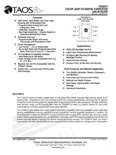
10 2. Block Diagrams of Si5351B and Si5351C 8-Output DevicesOSCXAXBPLLVCXOR0R1 CLK0 CLK1 VDDOAR2R3 CLK2 CLK3 VDDOBR4R5 CLK4 CLK5 VDDOCR6R7 CLK6 CLK7 VDDODM ultiSynth 0 MultiSynth 1 MultiSynth 2 MultiSynth 3 MultiSynth 4 MultiSynth 5 MultiSynth 6 MultiSynth 7 VCVDDGNDSi5351 BSCLSDAC ontrol LogicOEBSSENI2C Interface20-QFN, 24-QSOPR0R1 CLK0 CLK1 VDDOAR2R3 CLK2 CLK3 VDDOBR4R5 CLK4 CLK5 VDDOCR6R7 CLK6 CLK7 VDDODM ultiSynth 0 MultiSynth 1 MultiSynth 2 MultiSynth 3 MultiSynth 4 MultiSynth 5 MultiSynth 6 MultiSynth 7 VDDGNDSi5351 CPLLAPLLBXAXBOSCCLKINSCLSDAC ontrol LogicINTROEBI2C Interface20-QFN, 24-QSOPSi5351A/B/CPreliminary Rev. Functional DescriptionThe Si5351 is a versatile I2C programmable clock generator that is ideally suited for replacing crystals, crystaloscillators, VCXOs, PLLs, and buffers. A block diagram showing the general architecture of the Si5351 is shown inFigure 3. The device consists of an input stage, two synthesis stages, and an output stage.