1 Calculation Models For Ultimate Limit States
Found 11 free book(s)
08 Calculation models for Ultimate Limit States (Smith)
www.eurocode7.comMicrosoft PowerPoint - 08 Calculation models for Ultimate Limit States (Smith).pptx Author: Geocentrix Created Date: 3/30/2011 11:18:03 AM ...

Bridge Design to Eurocodes Worked examples
eurocodes.jrc.ec.europa.eu2.4.2 ULTIMATE LIMIT STATES . 23 . 2.4.3 SERVICEABILITY LIMIT STATES ... assisted by testing . 26 . 2.7 EN 1990 Section 6 – Limit states design and Annex A2 – Application for bridges . 26 . 2.7.1 DESIGN VALUES . 26 . 2.7.2 ULTIMATE LIMIT STATES ... A sample analytical method for bearing resistance calculation . APPENDIX C . C-1 . Examples ...

TITLE 2. STRUCTURAL ANALYSIS
www.mitma.gob.esthe structure in order to check the ultimate limit states and serviceability limit states defined in Section 8. Such an analysis must be conducted for the different design situations given in Section 7 using adequate structural models that consider the influence of all relevant variables. Section 18. Idealisation of the structure . 18.1.

EN 1993-1-5: Eurocode 3: Design of steel structures - Part ...
www.phd.eng.br(J)P The effects of shear lag and plate buckling shall be taken into account at the ultimate, serviceability or fatigue limit states. NOTE: Partial factors /1.;10 and }<.,11 used in this part are defined for different applications in the National Annexes of EN 1993-1 to EN 1993-6. 2.2 Effective width models …

EN 1992-1-1: Eurocode 2: Design of concrete structures ...
www.phd.eng.br5.3.1 Structural models for overall analysis 5.3.2 Geometric data 5.3.2.1 Effective width of flanges (all limit states) 5.3.2.2 Effective span of beams and slabs in buildings 5.4 Linear elastic analysis 5.5 Linear analysis with limited redistribution 5.6 Plastic analysis 5.6.1 General 5.6.2 Plastic analysis for beams, frames and slabs
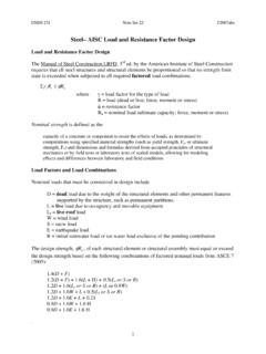
Steel– AISC Load and Resistance Factor Design
faculty-legacy.arch.tamu.eduThe nominal flexural strength Mn is the lowest value obtained according to the limit states of 1. yielding 2. lateral-torsional buckling 3. flange local buckling 4. web local buckling For a laterally braced compact section (one for which the plastic moment can be reached before local buckling) only the limit state of yielding is applicable.

Fatigue Analysis, Damage calculation, Rainflow counting
training.dewesoft.comIn this case, the Palmgren-Miner damage accumulation hypothesis states that each cycle with amplitude Si uses a fraction 1 / Ni of the total life. Thus the total fatigue damage D is given by equation: where ni is the number of cycles with amplitude Si. Fatigue failure occurs when the damage D exceeds one.

DESIGN OF ALL-BOLTED EXTENDED DOUBLE ANGLE, …
www.aisc.orgwill be used to determine applicable limit states and to develop a rational design procedure for all-bolted extended single angle, double angle, and tee connections. The scope of this project includes a review of past research done in the area of

THE STRUT-AND-TIE MODEL
cpb-us-e1.wpmucdn.com1 ' 0.85 0.8 170 c c cu f f f ≤ + = e where: e 1 = (e s + 0.002) cot2 a s f cu = the limiting compressive stress a s = the smallest angle between the compressive strut and adjoining tension ties (DEG) e s = the tensile strain in the concrete in the direction of the tension tie (IN/IN)
EN 1997-1: Eurocode 7: Geotechnical design - Part 1 ...
www.ngm2016.comEUROPEAN STANDARD EN 1997 .. 1 NORME EUROPEENNE EUROpAISCHE NORM November 2004 ICS 91.120.20 Supersedes ENV 1997-1'1994 English version Eurocode 7: Geotechnical design -Part 1: General rules Eurocode 7: Calcul geotechnique -Partie 1: Regles
Eurocode 7: Geotechnical design
geotechnicaldesign.infoEUROPEAN STANDARD NORME EUROPÉENNE EUROPÄI SCHE NORM EN 1997-1 November 2004 ICS 91.120.20 Supersedes ENV 1997-1:1994 English version Eurocode 7: Geotechnical design - Part 1: General rules