5 voltage regulator evaluation board
Found 7 free book(s)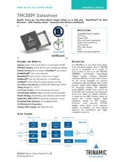
TMC2209 Datasheet - Trinamic
www.trinamic.comTRINAMICs universal evaluation board system which provides a convenient handling of the hardware as well as a user-friendly software tool for evaluation. The TMC2209 evaluation ... 5V Voltage regulator charge pump opt. ext. clock CLK_IN 10-16MHz 3.3V or 5V I/O voltage 100n Analog Scaling VREF Programmable Diagnostic Outputs Configuration ...

Single-Chip HID USB to SMBus Master Bridge CP2112 Data …
www.silabs.com3.1.4 Voltage Regulator Table 3.4. Voltage Regulator Parameter Symbol Test Condition Min Typ Max Unit Input Voltage Range VREGIN 3.0 — 5.25 V Output Voltage VDD Output Current = 1 to 100 mA1 3.3 3.45 3.6 V VBUS Detection Input Threshold VIH-VBUS 2.5 — — V Bias Current IREG — — 120 µA Note: 1.The maximum regulator supply current is ...

Low Power, 8.5 mW, 2.3 V to 5.5 V, Programmable Waveform ...
www.analog.comThis 2.5 V is generated from VDD using an on-board regulator when VDD exceeds 2.7 V. The regulator requires a decoupling capacitor of 100 nF typical, which is connected from CAP/2.5V to DGND. If VDD is less than or equal to 2.7 V, CAP/2.5V should be tied directly to VDD to bypass the on-board regulator.

FT2232H Mini Module - FTDI
www.ftdichip.comUSB bus (VBUS) and connects it to the voltage regulator input on the FT2232H Mini Module. The voltage regulator, in turn, provides V3V3, VPLL and VUSB power inputs to the FT2232H chip. 2) Connect V3V3 to VIO (CN2, pins 1, 3 & 5 to CN2, pins 11 & 21 and CN3, pins 12 & 22).
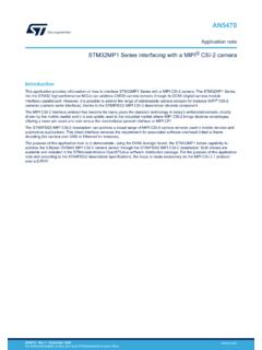
STM32MP1 Series interfacing with a MIPI® CSI-2 camera ...
www.st.comThis mezzanine board is designed to fit the Avenger96 board through both high and low-speed expansion connectors for the STM32MP157 line. It allows connecting the OV5640 module camera over MIPI CSI-2 for evaluation purposes. This board can connect a serial console, for instance GPIO PD1 and PB2 corresponding to UART4_TX and UART4_RX.

stm32
riptutorial.comDiscovery, a Nucleo or an Eval board, which come with an on-board SWD (Serial Wire Debug) programmer/debugger called ST-Link. Creating a project This example will use an STM32F4 Discovery kit, which features an STM32F407VG microcontroller. (Any other board can be used as well.) 1. Open SW4STM32 and create a new C project: File → New → C Project
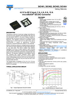
4.5 V to 60 V Input, 2 A, 4 A, 6 A, 10 A microBUCK DC/DC ...
www.vishay.comcompatible 5 mm by 5 mm lead (Pb)-free power enhanced MLP55-27L package. TYPICAL APPLICATION CIRCUIT Fig. 1 - Typical Application Circuit for SiC46x FEATURES • Versatile - Single supply operation from 4.5 V to 60 V input voltage - Adjustable output voltage down to 0.8 V - Scalable solution 2 A (SiC464), 4 A (SiC463), 6 A (SiC462), 10 A (SiC461)