Chapter 2 Stress And Strain Axial Loading
Found 9 free book(s)
Roark’sFormulas forStressandStrain
materiales.azc.uam.mxj Stress concentrations are presented in Chapter 17. j Part 2, Chapter 2, is completely revised, providing a more compre-hensive and modern presentation of stress and strain transforma-tions. j Experimental Methods. Chapter 6, is expanded, presenting more coverage on electrical strain gages and providing tables of equations
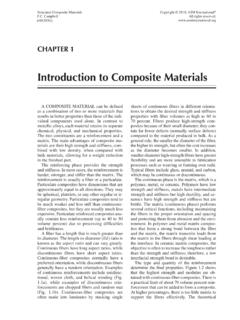
Introduction to Composite Materials
www.asminternational.orgtorted into a parallelogram, a shear strain g xy is induced as a result of coupling between the axial strains e xx and e yy. If the fibers are aligned parallel to the direc-tion of applied stress, as in the lower portion of Fig. 1.7 Shear coupling in a 45° ply. Source: Ref 1
Gusset Plate Stress 7a - ARC Structural
arcstructural.comDietrich (1999) presented the results of six cyclic tests of 2-scale double gusset plate connections that were representative of the connections for the San Francisco-Oakland Bay Bridge. The specimens were 4-in. and a-in. plates of A36 steel. The brace members connected to the gusset plates were loaded with axial load and moment. Strain gages were
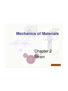
Chapter 2 Strain
web.ncyu.edu.twFigure 2.4 Stress-strain diagrams for various materials that fail without significant yielding. ( )2003 k /C l bli hi / h i However, the phenomenon of yielding is unique to structural steel. Other grades of steel, steel alloys, and other material do not yield, as indicated by the stress-strain curves of the materials shown in Fig.2.4..

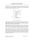
Chapter 5 Stresses in Beam (Basic Topics)
ocw.nthu.edu.twthe flexure formula gives results in the beam where the stress distribution is not disrupted by irregularities in the shape, or by discontinuous in loading (otherwise, stress concentration occurs) example 5-2 a steel wire of diameter d = 4 mm is bent around a cylindrical drum of radius R0 = 0.5 m E = 200 GPa "pl = 1200 MPa determine M and "max
6 INTRODUCTION TO COLUMN BUCKLING - steel-insdag.org
www.steel-insdag.orgElastic buckling stress (σcr) defined by (π 2E/ λ2) σcr (Mpa) λ = λ/r Fig. 4 Euler buckling relation between σ cr and λ 3.0 STRENGTH CURVE FOR AN IDEAL STRUT We will assume that the stress-strain relationship of the material of the column is defined by Fig. 5. A strut under compression can therefore resist only a maximum force given by fy.

Boundary Conditions and Loads - Altair University
altairuniversity.comtemperature is increased, it will produce thermal stress (at the xed end) as shown below. For thermal stress calculations, the input data needed is the temperature value on nodes, the ambient temperature, thermal conductivity, and the coecient of linear thermal expansion. 10. Gravity loading : Specify direction of gravity and material density.

Introduction to Finite Element Analysis (FEA) or Finite ...
www.engr.uvic.caThe Purpose of FEA Analytical Solution • Stress analysis for trusses, beams, and other simple structures are carried out based on dramatic simplification and idealization: – mass concentrated at the center of gravity – beam simplified as a line segment (same cross-section) • Design is based on the calculation results of the idealized structure & a large safety factor (1.5-3) given …

WELDS- STATIC AND FATIGUE STRENGTH – II
www.steel-insdag.org2.2.1 Static behaviour of butt welds For butt welds the most critical form of loading is tension applied in the transverse direction (Fig. 2). It has been observed from tests conducted on tensile coupons containing a full penetration butt weld normal to the applied load that the welded joint had higher strength than the parent metal itself.