Chapter 8 Phase Diagrams
Found 9 free book(s)
Teach Yourself Phase Diagrams and Phase Transformations
www.grantadesign.comThe Unit fits best with Chapter 19 in two instalments: Parts 1-4, dealing with phase diagrams; Parts 5-8, covering microstructure evolution in relation to phase diagrams. Teach Yourself Phase Diagrams A.4 HRS 03/11/2009 and Phase Transformations PART …

Thermodynamics and Phase Diagrams
www.crct.polymtl.caThe phase diagrams in Figs. 1-7 are only a small sampling of the many possible types of phase diagram sections. These diagrams and several other useful types of phase diagrams will be discussed in this chapter. Although these diagrams appear to 3
MATERIALS AND PROCESS IN MANUFACTURING Ninth Edition
dcetind.weebly.comChapter 4 Equilibrium Phase Diagrams and the Iron-Carbon System Page 26 Chapter 5 Heat Treatment Page 34 Chapter 6 Ferrous Metals and Alloys Page 42 Chapter 7 Nonferrous Metals and Alloys Page 49 Chapter 8 Nonmetallic Materials: Plastics, Elastomers, Ceramics, and Composites Page 54 Chapter 9 Material Selection Page 63 ...

Training Manual for Engineers on Solar PV System
wave.greenpeace.orgWith successful completion of the first phase of the Energy Sector Assistance Programme (ESAP), AEPC has initiated second phase ... 10.9 Installation Line Diagrams 214 ... Chapter 2 Features and Requirements for Skill Tests and Certification 3 CHAPTER 2

1734-UM006B, Encoder/Counter Modules User Manual
literature.rockwellautomation.comThe examples and diagrams in this manual are included solely for illustrative purposes. Because of the ma ny variables and requirements associated with any ... What This Chapter Contains Read this chapter to learn about types, features, and capabilities of ... phase versus 2 phase) for the count direction (up or down).
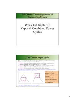
Week 13 Chapter 10 Combined Power Cycles
documents.uow.edu.auWeek 13 Chapter 10 Vapor & Combined Power ... Because: • Process 1-2Limiting the heat transfer processes to two-phase systems severely limits the maximum temperature that can be used in the cycle (374°C for water) ... • Draw the T‐s diagrams in both cycles.

Chapter 11: Phase Diagrams - CHERIC
www.cheric.orgAMSE 205 Spring ‘2016 Chapter 11 - 0 20 40 60 80 100 wt% Ni 1000 1100 1200 1300 1400 1500 1600 T(oC) L (liquid) α (FCC solid solution) Cu-Ni phase diagram 8 Phase Diagrams: Determination of phase(s) present

Healthcare interpretation of IEE Guidance Note 7 (Chapter ...
assets.publishing.service.gov.uk5 2.0 MEDICAL LOCATIONS 2.1 FOREWORD 2.1.1 These explanatory notes are based on the international standard for medical locations as detailed in IEC 60364-7-710.The latter forms the basis of IEE Guidance Note 7 - Chapter 10 `Medical Locations`. 2.1.2 The fundamental clauses of the IEC standard are listed and, where necessary, ` Notes` are included to amplify the content.
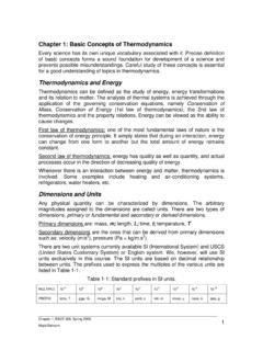
Chapter 1: Basic Concepts of Thermodynamics
www.mhtl.uwaterloo.caChapter 1, E&CE 309, Spring 2005. Majid Bahrami 8 Fig. 1-7: A four-process cycle in a P-V diagram. The state of a system is described by its properties. The state of a simple compressible system is completely specified by two independent, intensive properties. A system is called simple compressible system in the absence of electrical,