Connector ground splice location
Found 8 free book(s)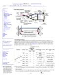
Trailer Wiring Diagrams | etrailer
www.actionoutboards.comSolve the problem by checking to make sure the ground wire is installed properly on the vehicle. To make sure you have a suitable ground, first connect the circuit tester's ground wire to the same location as the ground wire

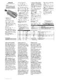
GROUP 90 - Car Diagnostic Tools and Information
cardiagnostics.beTSB Revision CIRCUIT DIAGRAMS 90-7 HOW TO READ CIRCUIT DIAGRAMS ITEM NO. CONNECTOR/ GROUNDING SYMBOL CONTENTS Connector and terminal marking 1 The male and female terminals

INSTALLATION AND OPERATION MANUA
www.pinsandsockets.nlwired to this connector. Also at this end of the wire harness there are two loose wires that provide power and ground. Dongle Wiring Push the black circular connector through the rectangular hole in

II Harness Kit 3-Port/2-Plug Isolation Module Light …
library.blizzardplows.comLit. No. 48266, Rev. 05 6 May 1, 2011 B29048, B29049, B29050, B29051, B29053, B29400-5 9. Check circuits for continuity. 10. Cover the splice with heatshrink tubing.
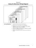
Section 2 Using the Electrical Wiring Diagram
www.autoshop101.comUsing the Electrical Wiring Diagram Body Electrical Diagnosis - Course L652 9 Junction blocks are used to distribute power and ground to the different circuits.
IMPULSE UNIVERSAL INSTALLATION - Hopkins …
www.hopkinstowingsolutions.comUNIVERSAL INSTALLATION White wire – ground/negative terminal (-) on battery Blue wire – trailer electric brakes Black wire – positive terminal (+) on battery

Wiring instructions For ElEctronic BrakE controls
site.drawtite.comwww .cequentgroup .com ©2010 Cequent Performance Products, Inc. P/N 98931-2011 Rev. A. 11/10 for 2011 403 b R ake cont R ols bRake contRols - tecHnIcal Wiring instructions For ElEctronic BrakE controls
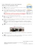
FUEL PRESSURE GAUGE AND SENSOR …
www.isspro.comForm No. IS1 69 (Rev. L 06/16/2016) ISSPRO, INC. • 2515 N.E. Riverside Way • Post Office Box 11177 • Portland, Oregon 97211-1899 503-528-3400 • …