Current loop
Found 6 free book(s)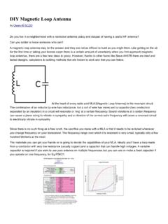
DIY Magnetic Loop Antenna
www.cvarc.orgFor example, my 30-10 Meter loop is 8.5 ft in circumference and 23% efficient at 10.1Mhz but 91% efficient at 28Mhz. This represents a difference of about 6dB or 1 S-Unit. The diameter of the conductor determines its resistance and this becomes important due to the large current flowing through the loop.

MAGNETIC LOOP ANTENNAS - Milford Amateur Radio Club
w8mrc.comWhat is a magnetic loop? • Radio waves travel by a wave of electric and magnetic fields at 90 degrees to each other. • Our regular antennas work by "recieving" the electric field portion of the radio wave. A small current is transduced on the antenna and the reciever amplifies it and converts it to audio.

Topologies for switch mode power supplies
www.st.com- Peak current of rectifier and switch is half the value of discontinuous mode - Low output ripple: C out (cont.) ≈ 0.5 C out (disc.) Figure 8: Continuous mode flyback waveforms ∆-Feedback loop difficult to stabilize (2 poles and right half plane zero) 9/18 APPLICATION NOTE

Operational Amplifier Circuits - MIT OpenCourseWare
ocw.mit.eduA current to voltage converter is an op amp circuit which accepts an input current and gives an output voltage that is proportional to the input current. The basic current to voltage converter is shown on Figure 5. This circuit arrangement is also called the transresistance amplifier. Iin R Vout N1 Figure 5. Current to voltage converter

LT8650S Dual Channel 4A, 42V, Synchronous Step-Down …
www.analog.comFeedback Pin Input Current VFB = 0.8V –20 20 nA Minimum On-Time ILOAD = 3A, SYNC ≥ 2V l 40 60 ns Oscillator Frequency RT = 133k RT = 35.7k RT = 15k l l l 270 0.94 1.85 300 1.0 2.00 330 1.06 2.15 kHz MHz MHz Top Power NMOS Current Limit 10 12 14 A Bottom Power NMOS Current Limit 6.5 8.5 10.5 A SW Leakage Current VIN = 42V, VSW = 0V,42V –2 ...
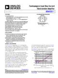
Femtoampere Input Bias Current Electrometer Amplifier Data ...
www.analog.comcurrent operational amplifier suitable for use as an electrometer that also includes an integrated guard buffer. It has an operating voltage range of 4.5 V to 16 V, enabling it to operate in conven-tional 5 V and 10 V single supply systems as well as ±2.5 V and ±5 V dual supply systems. It provides ultralow input bias currents that are production