Dc Electronic Load Load
Found 6 free book(s)
DC Electronic Load Applications and Examples - Mouser
www.mouser.comDC load. Failure to do this will measure the contact resistance of the power leads, overestimating the load regulation and output resistance of the power supply. Connect the voltmeter and DC load in parallel to the power supply's terminals (See Figure 3 for setup diagram). DC Load Setup Press the I-set button (for B&K Precision 8500) to change the
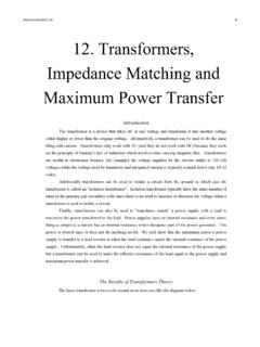
12. Transformers, Impedance Matching and Maximum Power ...
www.hunter.cuny.eduThe Maximum Power Transfer from a Power Supply to a Load Resistor Consider a power supply connected to a load resistor as indicated by the diagram below: The signal generator has an internal resistance as indicated and this is an intrinsic part of the power supply. The current in the above circuit is using Ohm's law I = (6) V HRLoad +Rinternal
NEMA Space-saving Contactors and Starters Specifications
literature.rockwellautomation.com- AC/DC electronic coil; with optional PLC interface 6…s8ez•Si - AC/DC electronic coil with PLC interface - "Mirror Contact" symbol on front Contacts 3 main poles with N.C. mirror feedback contacts Coil Voltages 20…500V, 50/60 Hz/DC Optional Accessories • Side-mount auxiliary contacts • Terminal shields • Terminal lugs • Terminal ...

DC to 9 GHz Vector Signal Generator Data Sheet AD9166
www.analog.comDC 4.3 dBm 9 GHz FIR85 enabled (2× NRZ) −9.5 dBm DEVICE CLOCK INPUT (CLK+, CLK−) Differential Input Power Load resistance (R LOAD Common-Mode Voltage AC-coupled 0.6 V Input Impedance1 3 GSPS input clock 90 Ω Maximum Input Frequency (f CLK) See Table 3 for more details 6400 MHz TEMPERATURE SENSOR

Orion -Tr Smart DC DC charger isolated - Victron Energy
www.victronenergy.comNo load input current < 80 mA < 100 mA < 100 mA < 80 mA Standby current Less than 1 mA Galvanic isolation 200 VDC between input, output and case Operating temperature range -20 to +55 °C (derate 3 % per °C above 40 °C) Humidity Max. 95 % non-condensing DC connection Screw terminals Maximum cable cross-section 16 mm² (AWG6)

Building a DC-DC Step-Down (Buck) Converter Circuit Using ...
www.egr.msu.eduThe circuit for the DC-DC step-down (Buck) converter would have the LM7809 voltage regulator, two capacitors with capacitance value of 0.33µF and 0.1µF. Figure 3 below shows the corresponding circuit, Figure 3: DC-DC step-down (Buck) converter circuit. Step 1: The LM7809 voltage regulator is placed in the desired position on the circuit board.