Design And Construction Of Seepage Cut
Found 6 free book(s)
SEWER DESIGN STANDARDS - New York City
www1.nyc.govprecast seepage basin ... lowest stage of sheeting or rock cut lines, from subgrade of trench to a min. height of two (2) feet above the outer top of the ... associate commissioner, design department of design and construction city of new york department of environmental protection standard for vitrified clay pipe
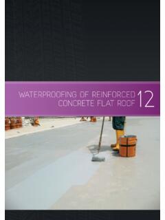
WATERPROOFING OF REINFORCED CONCRETE FLAT ROOF
bca.gov.sg12.2 DESIGN AND CONSTRUCTION OF FLAT ROOF ... First a small groove line can be cut on the parapet wall, then the L-shaped metal strip can be nailed on to the wall. Finally, the PVC membrane can be ... in order to prevent water seepage at the weak pipe/slab joint. Fig. 12.12 – PVC coated strips for perimeter terminations.
Example Geotechnical Report - Peterson Construction
petersonconstruction.comfoundation design and construction floor slab design and construction pavement design and construction 2.0 PROJECT INFORMATION 2.1 Project Description ITEM DESCRIPTION Site layout See Exhibit A-2, Exploration Plan Building Approximate 9,100-square foot, single story building with parking areas to the south and east of the building.

Railway Technical Website
www.railway-technical.comdesign. The older UK standard design was an elastic spike with a sprung, curved top which secures the rail. There are a number of variations seen around the world. One of the most popular is the "Pandrol" clip seen above. A resilient pad will be provided between the rail and the base plate and around the securing clip, where required to

SLOPE FACE STABILIZATION FOR CRITICAL SLOPE SURFACES
www.ccriindia.orgbuilt and compacted using common construction equipment. Generally, engineered embankment slopes are constructed in 203 millimeters (8 inch) layers. Each layer is compacted to a relative compaction of 90%. When constructing an embankment on existing hillsides, the existing hillside slopes are cut into a

CHAPTER 4 EARTH PRESSURE THEORY AND APPLICATION
dot.ca.govwalls are typically constructed in cut situations in which construction proceeds from the top down to the base of the wall. The vertical wall elements should extend below the potential failure plane associated with the retained soil mass. For these types of walls, economical wall heights up to 80 feet are feasible. 4-1