Diagram With Charger
Found 11 free book(s)
Orion-Tr Smart DC-DC Charger Isolated - Victron Energy
www.victronenergy.comFigure 4: Engine shutdown detection override connection diagram If the ignition switch in figure 4 is switched off, the charger will return to “engine shutdown detection” mode, it will not turn off the charger. To force enable/disable charging (i.e turn the ORION on/off) without the “engine shutdown detection” a remote option as given in

Electrical Design Standard Symbols - Red-Bag
www.red-bag.comsymbol for key diagram, m.v. and l.v. one line diagrams company document ns 501-502. cad name description symbol ns-03 turbine t ns-04 diesel d 06-04-01a generator g 06-04-01b motor m 06-04-01c motor with winding temperature detector m 02-17-06 charger / converter 06-14-03 rectifier 06-14-05 inverter 06-14-04 rectifier in full wave

MMPF0100, 14 Channel Configurable Power Management ...
www.nxp.com• Coin cell charger and RTC supply • DDR termination reference voltage • Power control logic with processor interface and event detection •I2C control • Individually programmable ON, OFF, and standby modes Figure 1. Simplified application diagram POWER MANAGEMENT PF0100 Applications: • Tablets •IPTV • eReaders • Set top boxes

AND9957 - On Board Charger (OBC) Three-phase PFC Converter
www.onsemi.comOn Board Charger (OBC) Three-phase PFC Converter AND9957/D Summary With the coming electrification of the automotive market, the need of battery chargers is more and more demanded. With the simple equation more power, shorter the recharge time is, a 3−phase supply is here considered which can provide up to ‘3x’ the power of a single− ...

OWNER'S MANUAL DieHard,
c.searspartsdirect.comBATTERY CHARGER 10/2 Amp Automatic ENGINE START 50 Amp Model No. 200.71222 CAUTION: Read all Safety Rules and Operating Instructions, ... Wiring Diagram GREEN 04o) BU<-, I 50A o ]::_ XFORMER-525 k _ 3. Before Using Your Battery Charger It is important to understand your charger's requirements. This section will tell you about your charger's ...

Everstart maxx battery charger user manual
solarwindependence.combattery charger, dating back to the 70's or earlier, tries to take a voltage measurement from the battery before launching into Also going to try to snag a wiring diagram, if I can.An Everstart battery charger will bring your battery back to life, if the battery has undamaged cells and will accept a charge.

Design of a Lead Acid Battery Charger System
ethesis.nitrkl.ac.inThe design of the hardware of lead acid battery charger is clearly illustrated by the block diagram shown below: Each individual module was designed and tested separately. After successful simulation and testing, they were put together to get the finalized version.
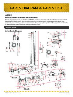
PArts DIAGrAm & PArts lIst - Minn Kota Motors
www.minnkotamotors.comThe parts diagram and parts list provides Minn Kota® WEEE compliance disassembly instructions. For more information about ... 124 2373241 t CABLE, USB REMOTE CHARGER *LINK ONLY* 1 126 490389-1 t CABLE, ETHERNET, 30' * LINK ONLY* 1 128 92-300-155 BRUSH END HSG, 112# 1 130 2375400 SHRINK TUBE-1/4 OD X 1-3/4 2
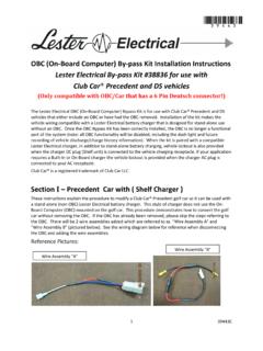
OBC (On-Board Computer) By-pass Kit Installation ...
www.golfcart.comLester Electrical charger, in addition to stand-alone battery charging, vehicle lockout is also provided when the charger DC plug (Shelf unit) is connected to the vehicle charging receptacle. If your application requires a Built-In or On-Board charger the vehicle lockout is provided when the charger AC plug is connected to your AC receptacle.

Operation and Safety Manual - JLG Industries
manuals2.jlg.comOperation and Safety Manual Original Instructions, Keep this manual with the machine at all times. ANSI ® Models 1930ES/2030ES/2630ES/ 2646ES/3246E

How To Wire Alternator - Vintage Auto Garage
vintageautogarage.comcharger. You want to have a fully charged battery when doing the next steps. Note: an alternator will not charge a dead battery because alternators take current to excite the field coil to make everything work. Step #9 Make sure the battery is connected negative to ground and the positive to the starter or starter solenoid (Figure 2).