Engineering And Design Coordinate Dimensioning
Found 10 free book(s)Fundamentals of Computer Aided Design
www.pages.drexel.eduFundamentals of Computer Aided Design Dimensions in Engineering Drawings MEM 201. Dept of Mechanical Engineering and Mechanics, Drexel University ... Dimensioning Angles in Views using COORDINATE method. Dept of Mechanical Engineering and Mechanics, Drexel University Dimensioning - Angles
Dimensioning Standards - Intro to Engineering Design (IED)
iedjohnson.weebly.comDimensioning Angles • Angled surface may be dimensioned using coordinate method to specify the two location distances of the angle. • Angled surfaces may also be dimensioned using the angular method by specifying one location for distance and the angle. Coordinate Method Angular Method
Engineering & Design: Geometric Dimensioning SECTION 5
tcdcinc.comEngineering & Design: Geometric Dimensioning 1 Introduction The concept of Geometric Dimensioning and Tolerancing (GD&T) was introduced by Stanley Parker from Scotland in the late 1930’s. However it was not used to any degree until World War II (WW II) because until then the vast majority of products were made in-house. The designer
NX 12 for Engineering Design - GitHub Pages
me5763.github.ioThe design process starts with identification of new customer needs and design variables to be improved, which are identified by the marketing personnel after getting feedback from the customers. Once the relevant design information is gathered, design specifications are …
Geometrical Dimensioning & Tolerancing (GD&T)
www.pages.drexel.edu• Use the same type of coordinate dimensioning system on the entire drawing. • Continuity of profile is necessary for CADD. Clearly define contour changes at the change or point of tangency. Define at least four points along an irregular profile. • Circular hole patterns may be defined with polar coordinate dimensioning.
Technical Drawing - BRL-CAD
brlcad.org• ASME Y14.100 -2004 Engineering Drawing Practices • ASME Y14.4M - 1989 Pictorial Drawing • ASME Y14.3M – Multi and Sectional View Drawings • ASME Y14.1 - 1995 Decimal Inch Drawing Sheet Size and Format • ASME Y14.5M – 1994 Geometric Dimensioning and Tolerancing • ASME Y14.13M - 1981 Mechanical Spring Representation
DIMENSIONING AND TOLERANCES - Mehmet Aladag
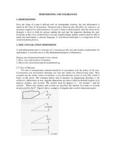
www.mehmetaladag.comDimensioning a drawing also identifies the tolerance (or accuracy) required for each dimension. If a part is dimensioned properly, then the intent of the designer is clear to both the person making the part and the inspector checking the part. Everyone in this circle of information (design, manufacturing, quality control) must be able to
Dimensioning and Tolerancing - School of Engineering
engineering.tcnj.eduDimensioning Geometrics is the science of specifying and tolerancing the shapes and locations of features on objects. Once the shape of a part is defined with an orthographic drawings, the size information is added also in the form of dimensions. Dimensioning a drawing also identifies the tolerance (or accuracy) required for each dimension.
Drafting - Engineering
file1.engineering.comCATIA Drafting CATIA® V5R14 Creating Views, Page 24 ©Wichita State University Front View The first view created is normally the front view. You can create a front view by defining the 3D object that you want to use and defining the plane that should be used to define the
Designer Quality Control Plan Guidelines
msdgc.orgMSDGC Designer Quality Control Plan Guidelines Page 5 of 13 04/23/2013 1.2.3 Engineer of Record: o Responsible for the design.


