Lead Free Wave Soldering
Found 9 free book(s)
1N5820 and 1N5822 are Preferred Devices Axial Lead Rectifiers
www.onsemi.com•Lead Temperature for Soldering Purposes: 260°C Max. for 10 Seconds ... 1N5822G Axial Lead (Pb-Free) 500 Units/Bag 1N5822RL Axial Lead 1500/Tape & Reel 1N5822RLG Axial Lead (Pb-Free) ... Circuit Half Wave Full Wave, Bridge Full Wave, Center Tapped* ...
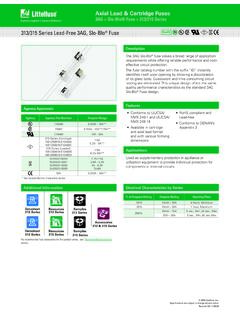
313/ 315 Series Lead-Free 3AG, Slo-Blo Fuse Pb PS E
www.littelfuse.comSoldering Parameters - Wave Soldering Dwell Time 0 20 40 60 80 100 120 140 160 180 200 220 240 260 280 300 0 10 20 30 40 50 60 70 80 90 10 0 11 0 12 0 13 0 14 0 15 0 16 0 17 0 18 0 19 0 20 0 21 0 22 0 23 0 24 0 Time (Seconds) Temperature (°C) - Measured on bottom side of boar d Preheat Time Cooling Time Wave Parameter Lead-Free Recommendation ...

PROFILE SUPPLEMENT FOR LEAD-free ALLOYS
aimsolder.comDocument Rev # 4 Page 5 of 6 TERMS AND DEFINITIONS Alloy, Tin Silver Copper (Sn-Ag-Cu): An alloy that is used as a lead-free solder consisting of tin, silver and copper as the main constituents.* Alloy, Tin Nickel Copper (Sn-Ni-Cu): An alloy that is used as a lead-free solder consisting of tin and copper considered to be applicable for wave or reflow soldering.

PROFILE SUPPLEMENT FOR WAVE SOLDERING PROCESS
aimsolder.comLead-Free Alloys 260 ... This defect information addresses common issues related to the wave soldering process. Soldering defects can be caused by a myriad of other process/material variables. However, there are three main inputs to forming a high quality solder joint and

Recommended Soldering Techniques
www.diodes.comWave soldering: Wave soldering is still widely employed for axial leaded devices and for mixed technology boards. Surface mount components can be wave soldered successfully if the recommendations in this document are followed. Surface mount components must first be mounted to the PCB with an adhesive before they can pass through the solder wave.
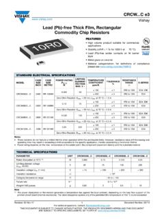
Lead (Pb)-free Thick Film, Rectangular Commodity Chip ...
www.vishay.comLead (Pb)-free Thick Film, Rectangular Commodity Chip Resistors FEATURES • High volume product suitable for commercial ... REFLOW SOLDERING WAVE SOLDERING INCH METRIC L W H T1 T2 a b l a b l 0402 1005 1.0 ± 0.10 0.5 ± 0.05 0.30 ± 0.05 0.25 ± 0.10 0.2 ± 0.1 0.4 0.6 0.5

Axial Lead Rectifiers
www.onsemi.comdownload the onsemi Soldering and Mounting Techniques Reference Manual, SOLDERRM/D. See detailed ordering and shipping information on page 6 of this data sheet. ORDERING INFORMATION MARKING DIAGRAM A =Assembly Location 1N581x =Device Number x= 7, 8, or 9 YY =Year WW =Work Week =Pb−Free Package A 1N581x YYWW (Note: Microdot may be in …
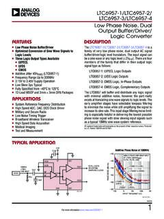
LTC6957-1/LTC6957-2/LTC6957-3/LTC6957-4 - Low Phase …
www.analog.comlead free finish tape and reel part marking* package description specified temperature range ltc6957idd-1#pbf ltc6957idd-1#trpbf lfqj 12-lead (3mm × 3mm) plastic dfn –40°c to 85°c ltc6957idd-2#pbf ltc6957idd-2#trpbf lfqk 12-lead (3mm × 3mm) plastic dfn –40°c to 85°c

CF / CFM Series Stackpole Electronics, Inc.
seielect.comSoldering iron recommended temperatures: 330°C to 350°C with minimum duration. Maximum number of reflow cycles: 3. Ramp DN (°C/sec) Wave Soldering – 100% Matte Tin / RoHS Compliant Terminations Preheat Time Description Maximum Recommended Minimum 80 seconds 70 seconds 60 seconds Temperature Diff. 140°C 120°C 100°C