Monitoring Monitoring Relays
Found 8 free book(s)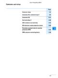
Contactors and relays - Eaton
www.moeller.netCMD contactor monitoring device 5-36. Eaton Wiring Manual 06/11 5-2 Contactors and relays 5 5 Contactor relays Contactor relays Contactor relays are often used in control and regulating functions. They are used in large quantities for the indirect control of motors, valves, clutches and heating
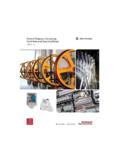
General Purpose, Interposing, Solid-State and Specialty Relays
literature.rockwellautomation.comSolid-State Relays Features 700-SH • High continuous load currents are achievable with heat sinks • LED indicator for Input/Logic ON/OFF status monitoring 700-SK • High-response speed model Input and output modules allow fl exibility General Purpose Relays 700-SH 700-HA700-HA 700-HB 700-SK
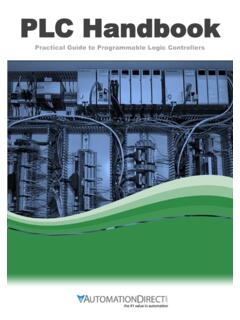
PLC Handbook - AutomationDirect
cdn.automationdirect.comCPU consists of a microprocessor, memory chip and other integrated circuits to control logic, monitoring and communications. The CPU has different operating modes. In programming mode the CPU will ... Before the days of the PLC the only way to control machinery was through the use of relays. Relays work by utilizing a coil that, when energized ...

Safety Relays - Namrata Trade Links
namratatradelinks.comCross fault monitoring Monitored or automatic reset Removable terminals Light curtain, E-stop or safety gate applications LED Indicators Green Power On Green CH1 Closed Green CH2 Closed Specifications. Safety Ratings Standards EN 954-1, ISO 13849-1, IEC/EN 60204-1, IEC 60947-4-1, IEC 60947-5-1, ANSI B11.19, AS4024.1
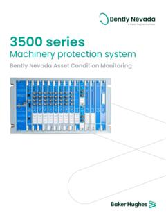
Bently Nevada 3500 Monitoring System
dam.bakerhughesds.comreliable monitoring system we have ever offered with extensive self-checking and fault tolerant design features. Connected Connecting to condition monitoring and diagnostic software has never been easier. With the 3500 there are no bulky external modules, no additional wiring, and no extra rack slots required.
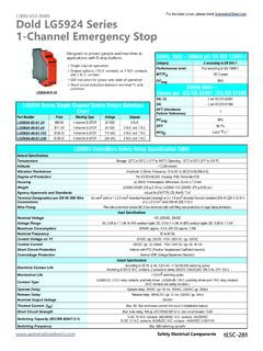
Dold LG5924 Series 1-Channel Emergency Stop
cdn.automationdirect.commonitoring logic A1(+)A2(-) Y1 Y2 13 23 33 41 14 24 34 42 K1 K2 K1 power. 24V. K2 K1/K2 S21(-) overvoltage-a nd shortc ircuit protection. monitoring logic. LG5924 Block Diagrams. Contact reinforcement by external contactors, 2-channel controlled. For currents > 5 A the output contacts can be reinforced by external contac-tors.

Intrinsic Safety Modules Selection Guide
literature.rockwellautomation.comrelays revert to their de-energized state and the light-emitting diode (LEDs) indicate the fa ult according to NAMUR NE44. Description 230V AC, 2-channel Signal type Digital input, relay output Supply Connection terminals 14, 15 Rated voltage 207…253V AC, 45…65 Hz Power loss 1.2 W Power consumption ≤1.3 W Input

MiCOM P141, P142, P143 - My Protection Guide
www.myprotectionguide.comTechnical Guide P14x/EN T/C54 MiCOM P141, P142, P143 FEEDER MANAGEMENT RELAYS MiCOM P141, P142, P143 CONTENT Issue Control