Pressure Calculations With Coefficient
Found 13 free book(s)
Industrial Ventilation Practical Concepts and Calculations
pdhonline.com8. Total Pressure 9. Fan Inlet Pressure Drop 10. Pressure Drop, Velocity and Velocity Pressure Relation 11. Pressure Head 12. Converting Head to Pressure 13. Coefficient of Entry 14. Hood Static Pressure 15. Rate Velocity Measurements 16. Air Density Correction Factors 17. Fan Average Capacities 18. Fan Laws 19. Fan Basic Characteristics 20.

C.11Emission Rate Calculations - US EPA
archive.epa.govStack Parameters/Calculations •Given – Pitot Coefficient, C p 0.84 – Velocity Equation Constant, K p 5130 •Measured – Stack Diameter, D S 26 in – Stack Area, A S 3.69 sf – Stack Pressure, P S 29.78 in Hg – Stack Temperature, T S 152 F, 612 R – Sample Pressure Drop, Δp 0.3087 in Hg Further stack calculations use the pitot ...

BURIED PIPE CALCULATIONS
www.adpf.aePressure class.... The Pressure class is related to the long term strength or HDB of the pipe as follows; ... X = Bedding coefficient The amount of deflection is a function of the soil load, Live load, Native soil characteristics at pipe elevation, pipe embedment material and density, trench width, haunching and pipe stiffness.

Motor Sizing Calculations
www.orientalmotor.comFrictional coefficient of sliding surfaces: 0.05 Ball screw efficiency: 0.9 Internal frictional coefficient of pilot pressure nut: 0 0.3 Ball screw shaft diameter: DB 0.6 inch (1.5 cm) Total length of ball screw: LB 23.6 inch (60 cm) Material of ball screw: Iron [density 4.64 oz/in3 (7.9 10-3 kg /cm3)] Pitch of ball screw: PB 0.6 inch (1.5 cm)

Structural Calculations Parking Garage CDRL 03-037.11
www.cityofthornton.netInternal Pressure Coefficient +/- 0.18 Resulting wind loads: Wind base shear: East/West 313 k North/South 183 k Components & cladding loads (based on 50sqft effective area): Interior roof zone 28.2 psf Roof end zone 38.0 psf Corner roof zone 38.0 psf Interior wall zone 27.0 psf Wall end zone 34.2 psf

Valve Sizing Calculations (Traditional Method)
www.emerson.com= Valve sizing coefficient determined experimentally for each style and size of valve, using water at standard conditions as the test fluid ∆P = Pressure differential in psi G = Specific gravity of fluid (water at 60°F = 1.0000) Thus, C v is numerically equal to the number of U.S. gallons of

DETERMINATION OF PRESSURE COEFFICIENT AROUND …
www.ripublication.compressure coefficient of the airfoil’s upper surface was negative and the lower surface was positive, thus the lift force of the airfoil is in the upward direction. It is found that larger the attack angle, greater is the difference of pressure coefficient between the lower and upper surface. The
Pipe Flow/Friction Factor Calculations using Excel ...
info.mheducation.comunits typically used in the equations. Several example calculations are included and spreadsheet screenshots are presented and discussed to illustrate the ways that spreadsheets can be used for pressure pipe flow/friction factor calculations, including both laminar and turbulent flow and cases in which minor losses are included in the calculations.
HVAC & Cooling Towers Practical Calculations
pdhonline.com11.0 – Overall Coefficient of Heat Transmission (“U”) 12.0 – Heat Loss Calculations 13.0 – Heat Conduction and Thermal Resistance 14.0 - Heat Loss due Air Change (ACH) and Ventilation 15 .0 – Typical Concrete Frames – Thermal Resistance 16.0 – Cooling Load Concepts 17.0 – CLTD/SCL/CLF - Methods of Load Calculations 18.0 ...
PRESSURE RELIEF VALVE ENGINEERING HANDBOOK
www.emerson.comOrifice Area and Coefficient of Discharge for Anderson Greenwood and Crosby ... of pressure relief valve sizing calculations. The program user must remember they are responsible for the correct determination of service conditions and the various data necessary for input to the sizing
A Design Example for a Rectangular Concrete Tank PCA ...
civil.colorado.eduFrom page 2-18 of PCA-R, the maximum vertical moment coefficient is 149, looking at the Mx table. This moment occurs at the center-bottom of the wall. Similarly, the My table gives a maximum horizontal moment coefficient of 99, located at the top ends of the wall. For the moment calculations qu = (1.3)(1.7)(945 pcf) = 2,089 psf

MAXIMUM PIPING OPERATING PRESSURE AS …
www.pumpfundamentals.comrelationship between pressure head and pressure is given in equation [4]. SG ppsi H ftfluid 2.31 ( ) ( ) [4] where (H) is the pressure head, (p) the pressure and (SG) the specific gravity of the fluid. If the shut-off pressure exceeds the allowable operating pressure as calculated by the ASME code, then pressure relief devices may have to be ...
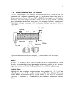
5.1 Shell-and-Tube Heat Exchangers
homepages.wmich.edu44 o t r d P P= (5.133) The tube clearance C t is obtained from Figure 5.21. C t = P t − d o (5.134) The number of tube N t can be predicted in fair approximation with the shell inside diameter D s. ShadeArea D N CTP s t π 2 4 = (5.135) where CTP is the tube count constant that accounts for the incomplete coverage of the shell diameter by the tubes, due to necessary clearance between the ...