Switch Diagrams
Found 7 free book(s)
TRIUMPH TR250 - TR6 WIRING DIAGRAMS
www.advanceautowire.comwiring diagrams. tr 250 f _ + ind + - _ w1 c1 w2 c2 p c4 b l 1 4 3 hazard switch t u r n s i g n a l s w i t c h turn signal flasher t s i n d i c a t o r hazard relay hazard flasher lh rear lh front rh front rh rear b l b+ + f starter starter solenoid battery ammeter lighting switch …
CF 500, CF 600 Circuit Diagrams
bodybuilder.navistar.comSwitch Positions (2) Within the schematic, all switches, sensors and relays are shown “at rest” (as if the Ignition Switch were OFF). Splices (3) A dashed line indicates that the splice is not shown completely. A reference is given to the page where the splice appears in full. It is also listed in the Index. 31 C270a 15 16 603 DG 27 603 DG ...
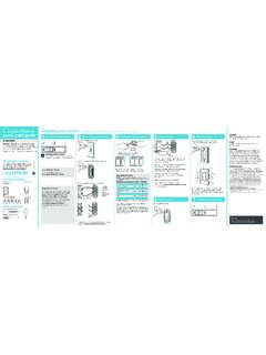
Wireless Installing your switch quick-start guide 1 2 3 4
www.casetawireless.comConnect the switch 5 Mount the switch 6 attach the wallplate 7 Turn power on at circuit breaker 2 remove existing switch from wall Remove the wallplate from switch. 3 remove side sections (if necessary) Remove the switch and pull it away from the wall. * If your light has more than one switch (called a 3-way), please visit www.casetawireless ...
A-1 HOW TO READ THE WIRING DIAGRAMS
www.evoscan.comA-4 HOW TO READ THE WIRING DIAGRAMS - How to Read Circuit Diagrams HOW TO READ CIRCUIT DIAGRAMS The circuit of each system from fuse (or fusible link) to earth is shown. The power supply is shown at the top and the earth at the bottom to …

Study Unit Understanding and Using Electronic Diagrams
www.workforcedevelopment.comSchematic Diagrams Schematic diagrams document the connection points and construction methods of electrical and electronic circuits. Figure 1shows a simple schematic diagram of a power sup-ply; on it you can see some of the conventions used. Figure 2 shows the symbols for such basic components as wires and Understanding and Using Electronic ...

Next Generation Guardmaster Safety Relay (GSR) Wiring …
literature.rockwellautomation.comNotes for Example Wiring Diagrams Note 1 In the wiring diagrams that are shown in this publication, the type of Allen-Bradley® Guardmaster® device is shown as an example to illustrate the circuit principle. For special applications, the choice of device type is based on the suitability of its characteristics for its intended use. Note 2
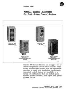
800-2.0 Typical Wiring Diagrams for Push Button Control ...
literature.rockwellautomation.comTypical Wiring Diagrams For Push Button Control Stations 3 Genera/ Information @ Each circuit is illustrated with a control circuit (continued) schematic or line diagram and a control station wiring diagram. l The schematic or line diagram includes all the components of the control circuit and indicates their