Transformer Rectifier Thyristor
Found 7 free book(s)
CHAPTER 12 THREE-PHASE CONTROLLED RECTIFIERS
www.worldcolleges.infoThe figure 12.1 shows the three-phase half-wave rectifier topology. To control the load voltage, the half wave rectifier uses three, common-cathode thyristor arrangement. In this figure, the power supply, and the transformer are assumed ideal. The thyristor will conduct (ON state), when the anode-to-cathode voltage v
Wiring Diagram Book - Daltco
www.daltco.comTransformer Disconnects98 Class 907098 Enclosure Selection Guide99 ... Wave Rectifier Full Wave Rectifier AC DC + DC AC Tunnel Diode Zener Diode Bidirectional Breakdown Diode Photosensitive Cell Triac SCR PUT NPN Transistor B C E PNP Transistor B C E UJT, N Base E B2 B1 UJT, P Base E B2 B1 Gate Turn-Of Thyristor G A K Standard Elementary ...

Siemens Standard Drives Application Handbook
cache.industry.siemens.comThe first electronic controllers used Thyristor (SCR) Rectifiers which controlled the voltage, and therefore the speed of DC motors. ... An induction motor works like a transformer. When the stator (the fixed, outer ... convert the AC supply to DC using a …
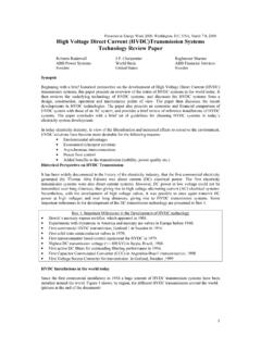
High Voltage Direct Current (HVDC)Transmission Systems ...
large.stanford.eduDC (rectifier) at the transmitting end, and from DC to AC (inverter) at the receiving end. There are three ways of achieving conversion: • Natural Commutated Converters. Natural commutated converters are most used in the HVDC systems as of today. The component that enables this conversion process is the thyristor,
Rectifiers - CERN
cds.cern.chA transformer is most often used both to introduce a galvanic isolation between the rectifier input and the AC mains and to adjust the rectifier AC input voltage to a level suitable for the required application. One of the parameters used to define the characteristics of the transformer is the Transformer Utilization Factor ( TUF ): DC DC PS 2 ...
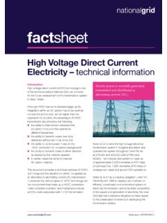
High Voltage Direct Current Electricity – technical ...
www.nationalgrid.comas a rectifier and converts the AC power into DC. A converter at the receiving terminal acts as an inverter and converts the DC power into AC. The connection between the converters may be by overhead line, cable, or both. Power electronic valves (essentially high powered, electronic switches) within the converters allow the

Common Electrical Symbols
www.reconelectrical.co.ukRectifier Inverter Primary cell - longer line positive, shorter line negative Battery Fuse link, rated current in amperes This is not a definitive list of all symbols used in electrical identification, but merely a guide to some of the more commonly used symbols. Due to the number of variants